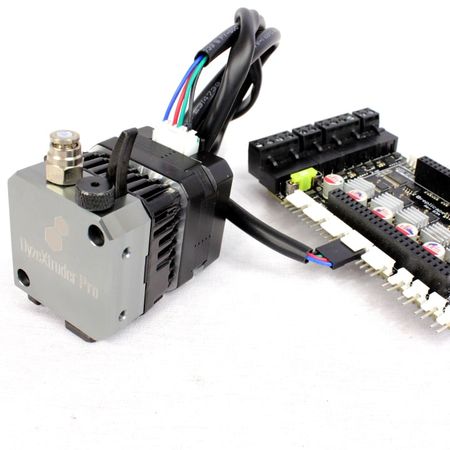
# Extruders DyzeXtruder GT DyzeXtruder Pro
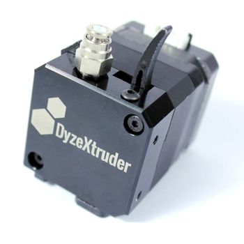
Make sure you have the right DyzeXtruder. The name and version can be confusing. Make sure yours looks like the one below:

# Installation
# Use an existing bracket
Yeggi (opens new window) is great source to find brackets and mounting solutions according to your printer.
# Design your own bracket
Get the latest CAD here: Drawing
TIP
Please note that you only need to mount the bracket on one side of the DyzExtruder.
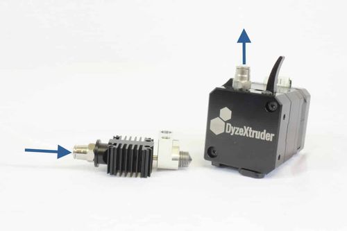
# Setup for Bowden
The DyzeXtruder products can work either way, either in direct drive using the groove mount system or by reversing the motor direction for Bowden setup.
- For the extruder alone, you need a length of 15mm, from the top.
- Add the height of your fitting.
- Mark the tubing to visualize the depth.
- Insert the tubing up to the mark. The filament must be well guided inside the extruder with this tubing.
# Method 1: Switch the cable orientation
The 4 pin cable connected to your board can be connected in the opposite order by making an 180° rotation. This will reverse the motor direction as the coils order are reversed.
# Method 2: Firmware modification
Firmware can reverse the extrusion direction. Find the corresponding option and reverse the logic.
# Marlin
#define INVERT_E0_DIR true
# Repetier
#define EXT0_INVERSE 1
# Smoothie
alpha_dir_pin !0.5
# Electronics
# Adjust your current setting
TIP
Some boards can adjust motor current with the firmware. If you don’t see any potentiometer, there is a high chance that your board has this feature. Refer to your main board documentation if you aren’t sure. The values for firmware controlled current are detailed below.
# 1. Adjust the current limiter on your stepper drivers.
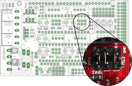
# How can I adjust my stepper drivers?
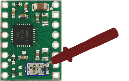
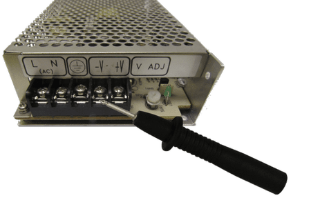
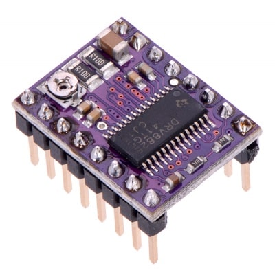
Simply take a current reading and adjust the current by turning the potentiometer with a screwdriver. The power must be ON in order to adjust the current. Make sure to take extra care not to touch the wrong pins with your multimeter leads.
Turn clockwise to increase the current.
TIP
Pololu original only: Take the reading as shown according to the multimeter leads with *. Also, turn counterclockwise to increase the current.
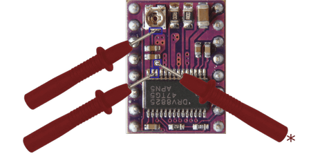
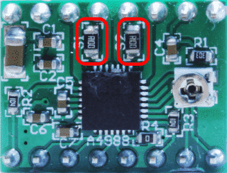
# How can I find my Rs resistance value?
The resistances are shown by the red rectangles. R100 means 0.100Ω. If each resistors are 0.100Ω, the Rs value is then 0.100Ω. The resistors value does not add up.
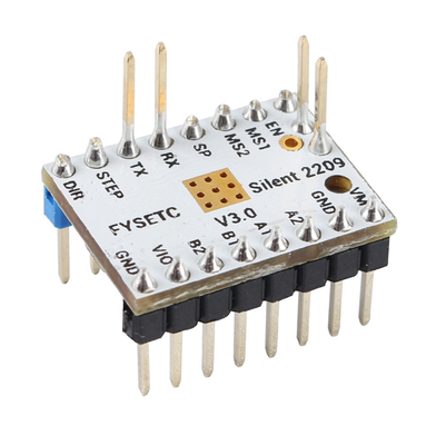
# How can I determine my stepper driver?
The easiest way to determine it is by checking the small writings on the top of the black chip. If you can’t read it, you may compare it with the circuits below.
- Allegro/A4988
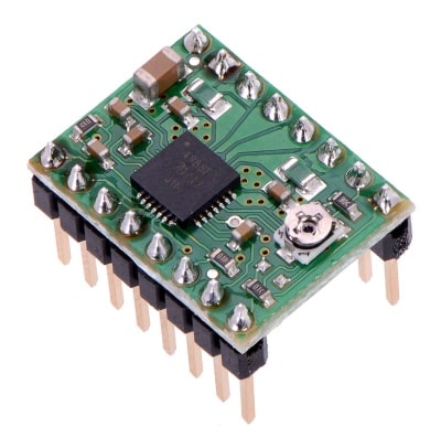
- Texas Instrument/DRV8825
- RAPS128
- TMC2209
# 2. Adjust your stepper drivers
TIP
A temperature rises of 35°C is normal (i.e., from 20°C at room temp up to 55°C) but can be lowered if you are using low Tg polymers.
Motor coils have a wide tolerance regarding resistance. Two identical extruders might require different stepper adjustments. Temperature is the easiest way to determine if the motor is running at the right current.
The DyzeXtruder GT requires less than 0.9A RMS to work.
| Stepper Driver | Voltage |
|---|---|
| A4988 [email protected]Ω | 0.36V |
| A4988 [email protected]Ω | 0.72V |
| A4988 [email protected]Ω | 1.44V |
| DRV8825 [email protected]Ω | 0.45V |
| RAPS128 | 0.82V |
| TMC2208 | 1.17V |
| TMC2209 | 1.27V |
| TMC2224 | 0.45V |
| TMC2130 | 1.27V |
# Adjust the current in the firmware Some boards only
| Board | MiniRambo | Rambo |
|---|---|---|
| File | pins_MINIRAMBO.h | Configuration_adv.h |
| Line | #define DEFAULT_PWM_MOTOR_CURRENT {1300, 1300, 1250} | #define DIGIPOT_MOTOR_CURRENT {135,135,135,135,135} |
| Current | Max: 1680 / 90%: 1512 | Max: 175 / 90%: 160 |
# Duet boards (RepRap Firmware)
With Duet, peak motor currents are set using the M906 command (opens new window). Please note that te peak current is 1.41 * RMS current. Our recommended 900mA RMS should be configured as 1270mA in peak current.
Simply add the following line to your config.g file:
M906 E1270
WARNING
For Duet 3 HC and Mini, start with a value as low as 350mA. Higher values might damage the motor. Before increasing the current, make sure the motor are within safe operating temperature, usually around 20°C over ambient temperature. It is also advised to use spreadCycle over stealthChop2.
# Plug the motor
WARNING
Ensure to use the cable provided with your extruder. Not all cables and motor have the same pinout.
Refer to your main board for proper extruder installation. If the motor is turning in the wrong direction, change the direction in the firmware directly or change the orientation of the motor.


# Firmware Configuration
# Find your step per mm value
Find the appropriate steps/mm value depending on your stepper driver and extruder model. Afterwards, use this value in your firmware.
# How can I determine my driving mode?
The example below is set HIGH, HIGH and HIGH for mode MS1, MS2 and MS3.
INFO
The steps/mm provided below are theoretical values to be used as a starting point. Steps/mm might need to be changed according to the printer extrusion flow and configurations. We recommend doing a calibration after the first installation. You should take the new values from calibration as your “steps per unit” for the firmware configuration.
# A4988
| Mode1 | Mode2 | Mode3 | Step | Steps/mm (DyzeXtruder GT) | Steps/mm (DyzeXtruder Pro) |
|---|---|---|---|---|---|
| High | High | High | 1/16 | 578 | 582 |
# DRV8825
| Mode1 | Mode2 | Mode3 | Step | Steps/mm (DyzeXtruder GT) | Steps/mm (DyzeXtruder Pro) |
|---|---|---|---|---|---|
| Low | Low | High | 1/16 | 578 | 582 |
| High | Low | High | 1/32 | 1156 | 1164 |
| Low | High | High | 1/32 | 1156 | 1164 |
| High | High | High | 1/32 | 1156 | 1164 |
# RAPS128 (THB6128)
| Mode1 | Mode2 | Mode3 | Step | Steps/mm (DyzeXtruder GT) | Steps/mm (DyzeXtruder Pro) |
|---|---|---|---|---|---|
| Low | Low | High | 1/16 | 578 | 582 |
| High | Low | High | 1/32 | 1156 | 1164 |
| Low | High | High | 1/64 | 2312 | 2328 |
| High | High | High | 1/128 | 4624 | 4656 |
# TMC2208
| Mode1 | Mode2 | Mode3 | Step | Steps/mm (DyzeXtruder GT) | Steps/mm (DyzeXtruder Pro) |
|---|---|---|---|---|---|
| High | High | NC | 1/16 | 578 | 582 |
# TMC2209
| Mode1 | Mode2 | Mode3 (SP) | Step | Steps/mm (DyzeXtruder GT) | Steps/mm (DyzeXtruder Pro) |
|---|---|---|---|---|---|
| High | High | High (SpreadCycle) | 1/16 | 578 | 582 |
# TMC2224
| Mode1 | Mode2 | Mode3 | Step | Steps/mm (DyzeXtruder GT) | Steps/mm (DyzeXtruder Pro) |
|---|---|---|---|---|---|
| Low | High | Low | 1/16 | 578 | 582 |
| High | High | Low | 1/32 | 1156 | 1164 |
# TMC2130
| SPI | Step | Steps/mm (DyzeXtruder GT) | Steps/mm (DyzeXtruder Pro) |
|---|---|---|---|
| Firmware configuration | 1/16 | 578 | 582 |
# Configure your firmware
# Marlin Firmware
#define DEFAULT_AXIS_STEPS_PER_UNIT {____,_____,____,XXX}
# Repetier Firmware
#define EXT0_STEPS_PER_MM XXX
# Smoothie Firmware
extruder_steps_per_mm XXX # Steps per mm for extruder stepper
# Redeem Firmware
Please note Redeem consider full steps for its configuration. For example, if you have a 250 steps/mm at 16 µsteps, your value is 250/16 = 15.625
steps_pr_mm_e = XXX
# Klipper Firmware
Open the printer.cfg file. In the [extruder] section, find and modify:
For Klipper 0.10.0 and the DyzeXtruder Pro:
rotation_distance: 31.06
gear_ratio: 5.65:1
#control: pid
#pid_Kp: 19.3
#pid_Ki: 2.1
#pid_Kd: 44.6
For Klipper 0.10.0 and the DyzeXtruder GT:
rotation_distance: 31.28
gear_ratio: 5.65:1
#control: pid
#pid_Kp: 19.3
#pid_Ki: 2.1
#pid_Kd: 44.6
WARNING
The rotation_distance value is a starting point and will need to be calibrated
For older versions of Klipper
step_distance: XXX
Where XXX is 1 divided by your steps per mm value
(ex: 0.001718 for DyzeXtruder Pro, TMC 2209 drivers and 16 microsteps, 1/582)
Find more info about steps per mm values here : Find your steps
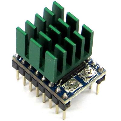
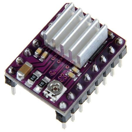
# Cooling
It is preferable to install a fan over the heatsink to help to cool the stepper driver. The high current set-up requires active cooling of the stepper driver in order to maintain a low enough temperature.
WARNING
Make sure the stepper driver has a heatsink installed with thermal paste or thermal adhesive. The heatsink should be positioned precisely and should not touch the contacts pins.
# Slicer Configuration
Configure your slicer with the following values listed below.
INFO
Depending on your slicer, the setting name might be slightly different.
| Extruder | Setting Name | Base Value | Maximum value |
|---|---|---|---|
| DyzeXtruder GT | Retraction speed | 25 mm/s (1500 mm/min) | 35 mm/s (2100 mm/min) |
| DyzeXtruder Pro | Retraction speed | 25 mm/s (1500 mm/min) | 35 mm/s (2100 mm/min) |
# How to use the extruder
# Insert a filament
Push the large lever closer to the push-fitting.
Engage the locking mechanism and release the lever. The locking mechanism should hold the lever in place.
Insert the filament.
Push the lever once more, the locking mechanism will release itself.
Gently release the lever.
# Remove a filament
Push the lever closer to the push-fitting.
Push the locking mechanism and release the lever. The locking mechanism should hold the lever in place.
Remove the filament.
Push the lever once more, the locking mechanism will release itself.
Gently release the lever.
# Install a HotEnd
Using a 2mm Allen, loosen the top button head cap screw by a few turns.
Using a 2mm Allen, loosen the bottom button head cap screw by a few turns too.
Using a 2mm Allen, slightly tighten the bottom button head cap screw until the GrooveMount plate touches the HotEnd.
You should be able to remove it and install it easily.
WARNING
This step must only be done once. Using the same hotend won’t require any more adjustments.
WARNING
Make sure the bottom adjustment screw is as close as possible to the GrooveMount plate. A bad adjustment could lead to a tilted hotend or could damage the GrooveMount plate.
Using a 2mm Allen, tighten the bottom button head cap screw until it touches the GrooveMount plate.
Position the HotEnd to your required orientation. Using a 2mm Allen, slightly tighten the top button head cap screw until the HotEnd is held in place.
# Remove a HotEnd
Using a 2mm Allen, loosen the top button head cap screw by a few turns.
Turn the hotend GrooveMount holder and remove the hotend.
# Liquid cool your extruder DyzeXtruder GT DyzeXtruder Pro
Remove the screws
Use a phillips screw driver and remove the 4 screws holding the back bell of the stepper motor.
WARNING
Do not remove the motor back bell.
WARNING
For the DyzeXtruder GT and Pro series, only remove two opposites screws. Remove the two screws that aren't aligned with the 2 screws front the front block. Do not remove all 4 screws.
Apply thermal paste
Apply thermal paste on the back bell of the stepper motor.
Install the liquid cooling block
Use a 2.5mm allen wrench and install 4 longer screws (M03x0.5×30) for holding the liquid cooling block.
WARNING
Make sure to remove the tape under the liquid cooling block before installing it!
PLEASE NOTE
The longer M02x0.5x30 are not provided with the extruder.
Install the tubing
Install your tubes inside the loop. There is no specific input or output on the liquid cooling block. Do not forget to install the hose clamps if your loop is already completed on the other end.
Crimp the tube clamps
Use a tube crimping plier and crimp the hose clamps.
# Maintenance
# Grease the gears
WARNING
A first check should be done during the first extruded spool to ensure the extruder is working properly. The extruder should then be checked every 50 kg extruded. Heated chamber should be checked more frequently than standard setups.
Lubricant type
Grease lubricant such as white lithium grease is optimal for the DyzeXtruder GT usage. ISO Viscosity grade should be between 150 and 220, or NLGI Class 2. Loctite LB 8042, MG Chemicals 8461-85ML or equivalent is suggested.
Remove the front screws
Using a 2.00mm allen tool, loosen the two front screws.
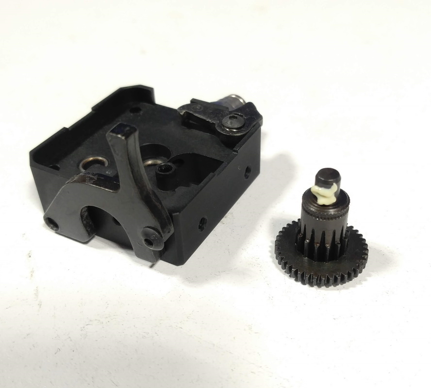
Open the extruder
Lift the two blocks from the motor. Separate them. If the gears are placed differently, place them as shown in the video.
2.1 Special step for the DyzeXtruder Pro
To access the central wheel of the DyzeXtruder Pro, start by removing the "Filament Guide." First, unscrew the M3x6 Flat head screw securing the guide. Once removed, you can easily pull out the filament guide, allowing access to the central wheel.
Visually check the gears
Inspect each gear to make sure there are no debris or damaged teeth.
Grease the motor
Using a brush, apply grease on the motor gear.
Grease the first gear
Using a brush, apply grease on both gears.
Grease the second gear
Using a brush, apply grease on both gears.
Grease the third gear
Using a brush, apply grease on the last gear.
Place the gears
Replace the gears inside the back block. Make sure not to invert them. Refer to the video below.
Place the blocks together
Carefully stack both block together.
Place the blocks on the motor
Place the blocks on the motor. You might need to turn it a little bit so the teeth take their position.
Tighten the screws
Using a 2.00mm allen tool, tighten the two front screws.
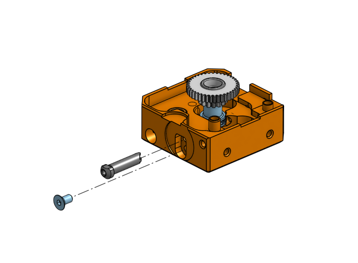
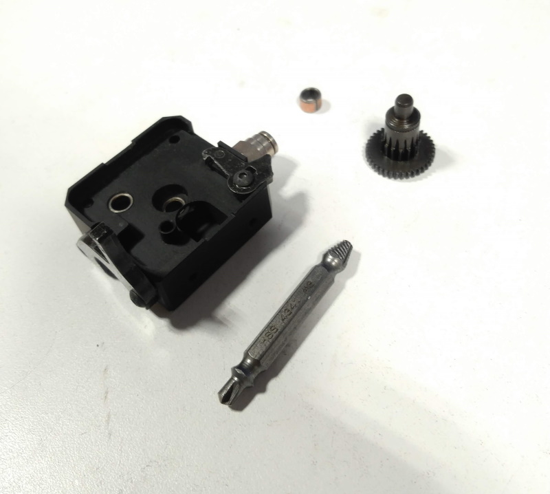
# Change the traction gear
Required tools
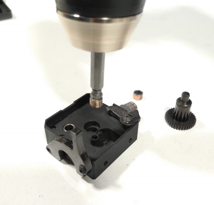
You'll need a screw extractor to remove the center bushing. Make sure the tool is designed for 5mm holes.
Remove the center bushing
WARNING
Be carefull when using a power tool with the screw extraction tool. A high torque is required to safely remove the bushing. Make sure the black block is well held in a vise or similar work holding tool.
Using the screw extractor, remove the center bushing.
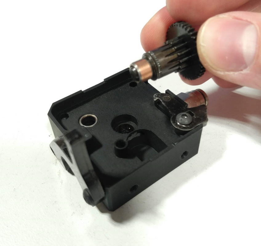
Position a new bushing
Insert a new bushing on the traction gear shaft.
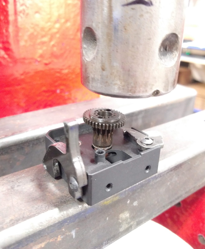
Press the new bushing
Using an arbor press, carefully insert the bushing in its hole.
Grease the gear and the shaft
Apply great to the shaft and gears.