# Liquid Cooling
Here are some guidelines when using a liquid cooling system with our products. You can buy directly our industrial liquid cooling kit (contact us), order it from a specialized manufacturer, or even build your own.
# Dyze Design Liquid Cooling Kit
A kit will contain all the standard parts you need to get the liquid system up and running. Our Dyze Design Liquid Cooling Kit is tailored for our products, both in term of material and performance. Other kits can also be used, but care must be taken regarding possible galvanic corrosion due to the presence of copper and brass pipes.
The Dyze Design Liquid Cooling Kit contains the following elements:
- A reliable 800 L/h pump
- A 300 ml clear reservoir
- A 360x120mm radiator
- Three low noise 120x120mm fans
# First setup of your cooling unit
IMPORTANT
Make sure to follow the setup instructions step by step. Failure to do so may result in a poorly calibrated system, malfunctions or breaks.
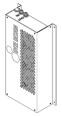
Mount the Cooling Unit
Use M6, M5 or M4 screws to mount the unit vertically. Four extra M4 thread forming strip-resistant torx screws for sheet metal are provided for this purpose. Refer to the adjacent figure for the footprint and bolt pattern.
WARNING
Do not mount the Cooling Unit horizontally. Doing so will damage the pump. The input/output nozzles should always be pointing upwards.
WARNING
The Cooling Unit should be fastened well enough to prevent it from tipping over or shaking excessively.
Route the tubing
Install the tubing on the printer. The tubing should pass from the Cooling Unit to the part you want cooled and back to the Cooling Unit. Make sure to follow the tube routing guidelines of this guide (see the “Tube routing” section of the present guide).
It is recommended that the tubing follow the cable chain to ensure no tubing ever gets pinched. The bend radius of the tubing should also never be smaller than 2” (50mm). Always test different positions of the print head once the tubing has been installed to ensure that no pinches or kinks appear in the tubing.
Connect the tubing
Remove the compression rings from the fittings. Pass the input (hot water from the hotend) and output (cold water from the Cooling Unit) tubes through the ring and install them on the nozzles. Tightly screw the rings over the nozzles while maintaining the tubes in place.
WARNING
Do not over-tighten the rings as they could damage the tubes. The rings will be sufficiently tight if you use your fingers.
Fill the Liquid Cooling System
Fill the provided squeeze bottle with your coolant fluid and/or distilled water. Open the fill port and insert the tube of the bottle as deep as possible into it. It is recommended to use a towel or rag around the fill port to ensure that no coolant makes its way to the electronics of the Liquid Cooling Unit. The level of the tank can be seen on the slot situated on the side of the Cooling Unit.
Fill the reservoir with coolant and/or distilled water until the reservoir is full (the level line is too high to be seen through the slot anymore). Note that a refill of the squeeze bottle might be needed.
WARNING
Ensure no water makes its way inside the frame to the electronic components.
Connect the wiring
With your power supply powered off, using the terminal blocks’ clamps, connect and secure the Cooling Unit’s power supply’s bare wires.
See Wiring Section
WARNING
Make sure the wires are not live while connecting them.
Fill the remainder of the system
Refill the provided squeeze bottle with your coolant fluid and/or distilled water. Power on your power supply. The pump will turn on too and start draining the liquid in the reservoir. Immediately start refilling the reservoir until the liquid level stabilizes at full capacity (the level line is too high to be seen through the slot anymore).
The fill port should be left open during the first 5 minutes of function to ensure that any air still trapped in the system makes its way out. Once 5 minutes have passed, close the fill port with the provided plug.
WARNING
The pump should never run dry as it may sustain damage doing so. If you do not think you will be able to refill the reservoir quickly enough as it gets drained, power the system on for a short period of time, then turn the system off again before refilling the reservoir. Repeat until the level in the reservoir stabilizes.
Stay Cool!
Close the fill port using the provided G1/4 plug. Your Dyze Design Liquid Cooling Unit is now ready to protect your prints!
# General Information
# How it Works
The Cooling Unit cools your system by running liquid through the hot elements of your printer and through a radiator which cools the coolant. This offers a reliable means of cooling any overheated part of your system.
# What’s included
| Item | Quantity |
|---|---|
| Liquid Cooling Unit | 1 |
| ¼” ID, ⅜” OD soft high temperature rubber tubing (8m) | 1 |
| Mounting hardware (M4 thread forming strip-resistant torx screws for sheet metal) | 4 |
| Filling system (Squeeze bottle) | 1 |
# What’s required
You might need more tubing than provided with the Cooling Unit, depending on your setup. You may use these types of tubings:
- ¼” ID, ⅜” OD soft high temperature rubber tubing (opens new window)
- Any other high temperature soft tubing with ID 6.5 ± 0.5mm and OD 9.5 ± 0.5mm
(ID 0.26 ± 0.02” and OD 0.37 ± 0.02”).
Cooling blocks that attach to the parts to cool (not necessary with liquid cooling embedded parts like the Typhoon™ or the Pulsar™):
Proper cooling agents:
- Deionized water with about 5ppm of minerals is preferred .
- Corrosion inhibitors should be added. Cars and computer liquid cooling solutions will work.
- Biocide should be added, although it is often included in the above suggestions.
# Mounting
The Cooling Unit should be mounted close to the parts you want to cool. While it can be placed relatively far away from your system, certain factors will affect the cooling power of your Cooling Unit. Following are recommendations for the mounting location of your Cooling Unit:
Mount the Unit at the location requiring the least amount of tubing.
As the tubing length increases, so does resistance to coolant flow. Longer tubing is detrimental to flow and cooling ability. The horizontal tubing length should not exceed 45 ft (13.7 m) (considering minimal elevation).Mount the Unit at a height that minimizes the maximum elevation in the tubing.
The higher the elevation, the harder it is for the pump to initially fill the system with water during the fill sequence. The maximum recommended height difference is 8 ft (2.4 m) (considering minimal tubing length).Make sure the tubing cannot get stuck or pinched in between moving parts and that it cannot bend too tightly.
Failure to do so will cause kinks and blockages. The system will detect those and will pause the print. The bend radius of the rubber tubing should not exceed 2” (50 mm).If your printer has a heated chamber, your Cooling Unit should not be installed inside it.
The Cooling Unit’s maximum working temperature is 100 °F (40 °C).
# Wiring
The Cooling Unit needs 12V to power all the electrical devices: pump, fans, sensors and circuit board.
Power Input Specifications:
| Parameter | Min | Typical | Max |
|---|---|---|---|
| Voltage Input (VDC) | 12 | 13.5 | |
| Current (A) | 2 |
The Liquid Cooling System's bottom pin receives the V+ connection, while the top pin receives the V- connection.

# Tube Routing
It is primordial for the tubes to be routed safely to avoid any possibility of them losing water-tightness or impeding flow. The tubes should be routed from the Cooling Unit to the cooled components and back in a way to avoid the tubes from rubbing on sharp edges, touching heated parts, kinking, or getting caught, pulled apart, stretched, pinched or crushed by moving components or throughout your 3D printer’s entire range of motion.
Here are a few tips on how to do so:
- Use grommets whenever the tubes go through panels
- Avoid any tight bends
- Use cable-chains or piggy-back on existing cable-chains
- Loosely attach the tube to the printer’s frame so that the tubes can slide if they need to
- Make the tube arrive and depart from above the hot end to avoid possible interference with the hot end, bed or print.
- Make sure that the tubes won’t droop down on the print and printing platform
- Test your routing by moving the printer through its entire possible range of motion while looking for any possibility the tubes might pinch, kink, touch sharp edges or heated parts, be too short, or get caught on another component.
WARNING
Do not power or fill the Cooling Unit before the tubes are completely safely routed and form a complete loop from the Cooling Unit to the cooled components and back to the Cooling Unit.
If you need to break the watertight loop (i.e. to add or remove a cooled component) from the Cooling Unit to the cooled components and back to the Cooling Unit while the Cooling Unit is filled or still has a substantial amount of fluid, you will need to follow these steps:
- Power off the Cooling Unit.
- Get a container (at least 2 liters) and some rags.
- Open the fill port.
- Tightly pinch the input tube from the Cooling Unit. It is recommended to use a clamp.
- Using rags to make sure no fluid makes its way inside of the Cooling Unit, unfasten the input tube from the Cooling Unit, place it into the container, unpinch the tube and let the fluid drain out completely.
- Pinch the tubbing right before and after the point where you want to break the watertight loop.
- You can now safely break the watertight loop with minimized risks of leakage.
WARNING
Not draining the input tube before unfastening it from the cooled components may cause the fluids to drain into the reservoir and cause an overflow and possibly damage the electronics.
# Maintenance
# Changing the Coolant
Over a long period of time, your coolant can become clouded with particules. These can end up accumulating and creating small chunks that can make flow difficult and eventually block it. It is then necessary to flush the old coolant and replace it with clean new coolant. To do so, you will need these tools:
- A large container, at least 2L
- Deionized water and/or coolant mix, about 2L
- Squeeze bottle
- A few rags, just in case
When all the tools are gathered, follow these steps:
Power the Cooling Unit off. Unplug it entirely.
Unplug the input tube from the Cooling Unit by unscrewing the compression fitting while holding the tube in place. Be sure to pinch the tubing so that a minimum amount of water spills out. Ensure no water makes its way inside the frame to the electronic components. Use rags around the input hole to soak any dripping.
Drop the end of the return tube in the bucket and unpinch it to let the old coolant flow out. Leave the tube in the container and make sure it stays inside.
Make sure no water made its way inside the frame to the electronic components during the previous steps. If water made its way inside, open the frame by unscrewing the 8 screws and dry the PCB using dry rags or wait 24h to let the coolant dry.
Plug the Cooling Unit and power it on. Wait until the reservoir is empty. As soon as it is, power the Cooling Unit off.
To make sure all the old coolant makes its way out, fill the reservoir with deionized water using the squeeze bottle inserted deep in the fill port.
Repeat steps 4 to 6 until the water that comes out of the Cooling Unit is clear and uncolored.
Fill the reservoir with the new coolant and/or distilled water until the reservoir is full (the level line is too high to be seen through the slot anymore).
Power on your power supply. The pump will turn on too and start draining the liquid in the reservoir. Immediately start refilling the reservoir until the liquid level stabilizes at full capacity (the level line is too high to be seen through the slot anymore).
WARNING
The pump should never run dry as it may sustain damage doing so.
Close the fill port using the provided G1/4 plug. Your system will now be ready to use.
# Build your own liquid cooling system
# Pump
- At least 300 L/h for a DyzEnd and DyzeXtruder
- At least 600 L/h for a Typhoon or a Pulsar
- Always running when the printer is
- Should be compatible with aluminum
- Head pressure should be more than the highest vertical distance the water will flow. Usually, 2 meters is adequate.
# Reservoir
- Transparent, to see water level
- 500ml capacity or more
- Fill port, greatly useful for maintenance
# Radiator
- Choose the right size for our product:
- 80mm radiator is enough for a DyzEnd and DyzeXtruder
- 120mm radiator is enough for a Typhoon or a Pulsar
- Should be made from aluminum. Copper and Brass radiator should be avoided to prevent galvanic corrosion
# Tubing
- High temperature type tubing is preferred
- Low bend radius to prevent kinking
- Always use tube clamp to secure the system
- Use cable chain and anti-kink coils where needed
# Liquid
WARNING
Never use tap, mineral or filtered water.
- Deionized water is preferred with about 5ppm of minerals
- Corrosion inhibitor should be added. Cars and computer liquid cooling solution will work
- Biocide should be added, often included in the above suggestions