# Pulsar™ Pellet Extruder
# Revision
| Date | Revision | Modifications |
|---|---|---|
| 2023-09-29 | R001 | Initial Release |
| 2026-06-12 | R002 | Added details regarding PWM frequency in Solid State Relays |
# What's in the box
| Item | Quantity |
|---|---|
| Pulsar™ Pellets Extrusion System | 1 |
| Pulsar™ Heatcore | 1 |
| Pulsar™ Extrusion Screw | 1 |
| M10 Socket Head | 1 |
| M10 Washer | 1 |
| NEMA23 Stepper Motor | 1 |
| 10A Solid State Relay (SSR) | 3 |
| Digital Stepper Motor Driver | 1 |
| Cable harness | 1 |
| Motor Cable | 1 |
| Dowel pins | 2 |
# What you need
- 3 x PT100 Amplifier circuits. Pulsar™ is using 3 PT100 for temperature sensing and you need a PT100 amplifier board to make them work with your printer controller board. Any amplifier circuit will work, as PT100 is pretty standard. We do however recommend using our own amplifier board available on our online store (opens new window).
- If you are using a Duet electronics and RepRapFirmware, it's not possible to use an analog amplifier. You'll need the digital RTD amplifier board (opens new window) designed for their ecosystem.
- Liquid-Cooling system (if you're not using Dyze Design Liquid Cooling Kit). You can find the minimum specs in our liquid cooling section.
- Automatic Pellet Feeding system (Optional). Pulsar™ can be fed with pellets by gravity but it was also designed to work with Dyze Design's automatic pellet feeding system. Contact us for more information or to purchase the system.
- [For best performance] A 48V power supply for the stepper motor.
WARNING
The Pulsar™ was designed to be actively cooled by a water loop. If you try to use it without a liquid cooling loop, you will experience issues.
WARNING
Purge the Pulsar™ extruder once the print is done. Using the appropriate purge compound for the material you processed will increase the lifecycle of the extruder & prevent clogs and jams. See the procedure “Purging the Pulsar”
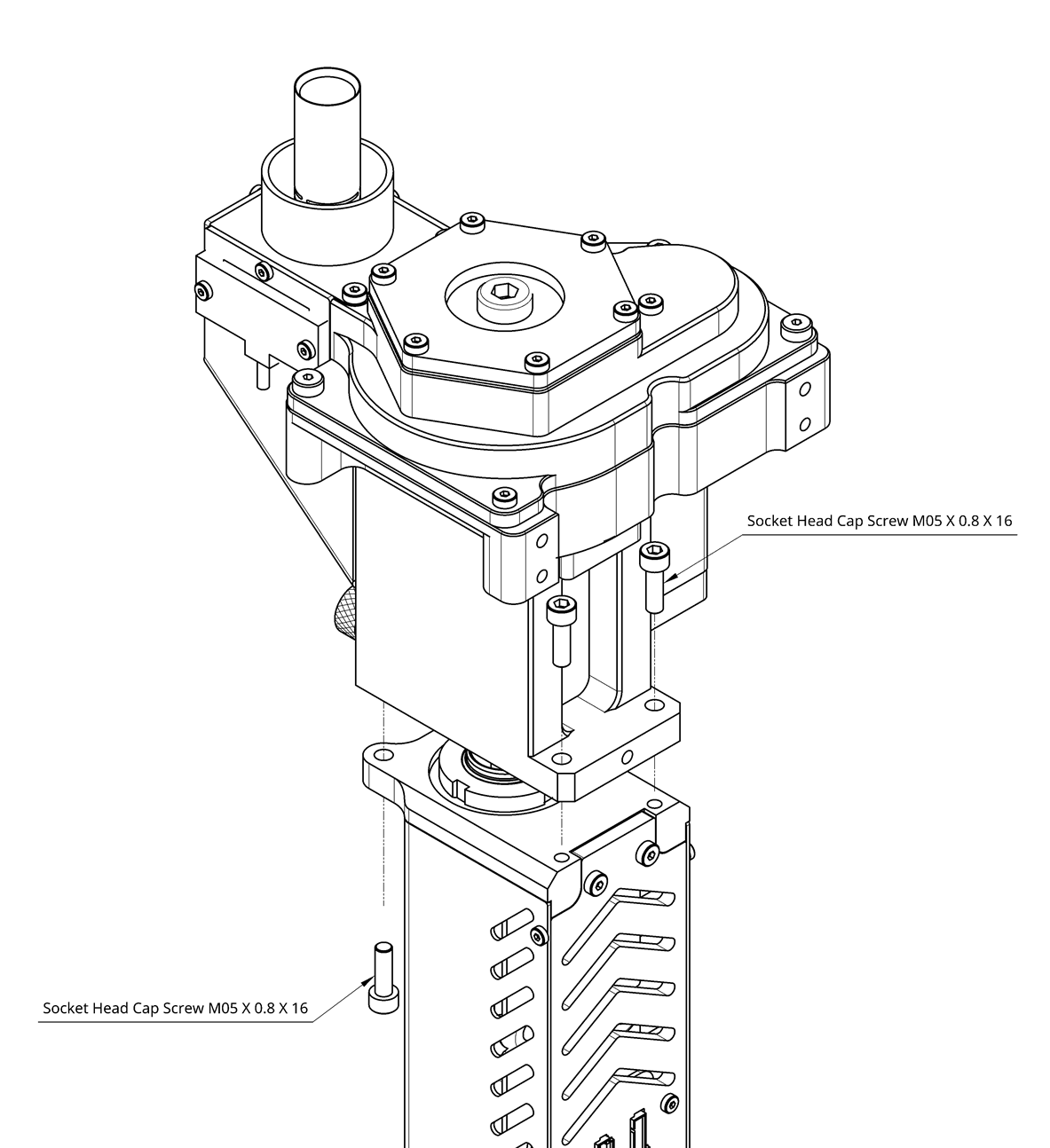
# Initial Assembly
To eliminate the risk of damage during transportation, the extrusion screw and Heatcore comes disassembled. Follow the procedure to have the machine ready for mounting.
What you need :
- 7 mm Allen key or Screwdriver
- 4 mm Allen Key or Screwdriver
- 4 * M5 Socket Head Screw
- M10 Socket Head Screw
- M10 Washer
- Extrusion Screw
- Pulsar™ Pellet Extrusion System
- Pulsar™ Heatcore
- Protective Gloves
- Place the Pulsar™ Extrusion System on a table with the hopper facing up.
- Insert the Extrusion Screw spline first in the Pellet Extrusion System and secure the Extrusion Screw in place using the M10 Washer and Socket Head Screw. Make sure the Extrusion Spline is properly inserted in the matching feature
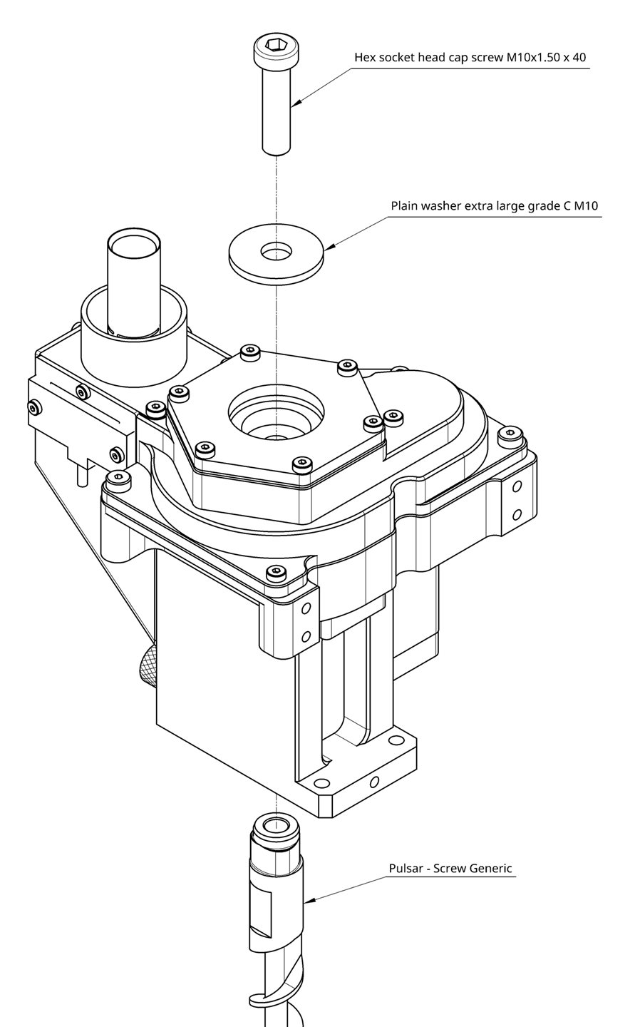
- Slide the Pulsar™ Heatcore over the Extrusion Screw
- Secure the Heatcore in place using the four M5 screws
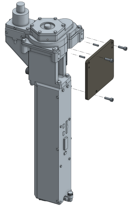
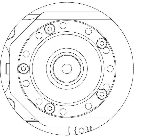
# Mounting
Mounting the Pulsar™ is done using 3 M5 screws with 2 dowel pins for accurate positioning. This ensures a robust assembly to your 3D printer or machinery.
- Threaded holes : M5 x 0.80. Minimum thread engagement of 8 mm
- Dowel Pins hole are 4.00 mm x 10.00 deep
Check out our drawing page to get the 3D STEP file. Design your bracket according to the available mounting options.
On the CAD file, consider the following references:
- 4.20mm holes are M5.00 x 0.80 threaded holes
- 4.00mm holes are reamed holes for dowels pins
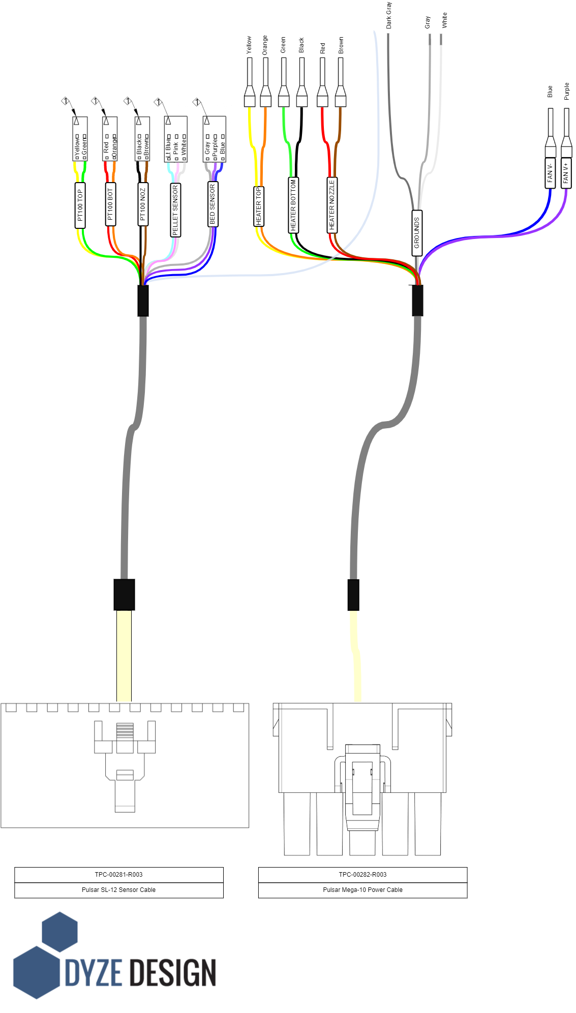
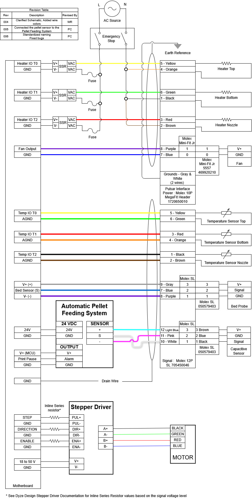
# Wiring
The Pulsar comes with two cable harnesses that are designed to connect from the barrel up to your electric box. The standard length is 2 meters. A diagram is shown below with more information about the electrical connections.
# Solid State Relay
Each heater has its own solid state relay (SSR). Three SSR is provided with the Pulsar™ in the box.
WARNING
Note on SSR Selection and Configuration The SSRs provided are zero-crossing types, which are ideal for reducing electrical noise but require specific timing configurations. Depending on your chosen firmware (such as Klipper, Marlin, or RepRapFirmware), you must configure the PWM frequency for these heater outputs to a low rate, typically around 2 to 3 Hz. Setting the frequency too high will prevent a zero-crossing SSR from switching correctly, leading to unstable temperature control or a complete failure to heat.
The fuse is optional but strongly suggested. Each fuse should be rated according to the power rating:
- Top heater, 500 Watts, 5A for 120VAC and 2.5A for 240VAC systems
- Middle heater, 350 Watts, 3.5A for 120VAC and 1.75A for 240VAC systems
- Nozzle heater, 250 Watts, 2.5A for 120VAC and 1.25A for 240VAC systems
Many pins can be used as the temperature output control. Your 3D Printer Controller (or motion controller) pins can be as below:
- The standard extruder output (E0, E1, E2, etc). These are usually rated at the same voltage as your main power supply (12VDC or 24VDC).
- Any available expansion pins. These can be determined by checking the 3D Printer Controller specification pins.
Please refer to the following diagram for wiring the Pulsar:
# Heaters
Heaters with coil heating elements can sometimes absorb moisture, particularly if they haven't been used for a while. This can lower the insulation resistance, potentially causing a small electrical current to leak to the ground. While this is often harmless, in some cases it can trip a GFCI (Ground Fault Circuit Interrupter) breaker.
To prevent this, especially when starting the heater for the first time or after a long period of disuse, you should perform a dehumidifying maintenance routine. This process, detailed below, will dry out the unit and restore proper insulation levels.
WARNING
You must run this procedure on the first startup. Skipping this step may damage the heater.
Dehumidifying Maintenance Routine
# Backplate Add-On Connectors
The Pulsar™ has three extra connectors on the backplate. One is for fans, another one is for a Z probe (bed sensor) and the third is for the included capacitive sensor mounted on the side of the material inlet (used for pellets presence in the inlet).
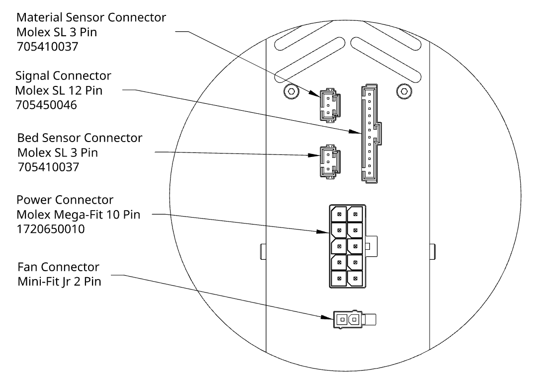
# Fan Connector
The fan connector mates with a Molex Mini-Fit Jr. The mating housing part number is 469920210 and the crimp is 0039000038.
| Pin 1 | Pin 2 |
|---|---|
| GND | V+ |
# Bed Sensor Connector
The bed sensor connector mates with a Molex SL. The mating housing part number is 50579403 and the crimp is 16020087.
| Pin 1 | Pin 2 | Pin 3 |
|---|---|---|
| Signal | GND | V+ |
# Capacitive Sensor Connector
The capacitive sensor (for pellets) connector mates with a Molex SL. The mating housing part number is 50579403 and the crimp is 16020087.
| Pin 1 | Pin 2 | Pin 3 |
|---|---|---|
| Signal | Gnd | V+ |
The capacitive sensor is supplied with the Pulsar. It needs to be mounted and plugged in the backplate.
# Adjusting the sensor
The sensor is capacitive, meaning that it doesn’t need specific material to operate. However, different materials may need different sensor settings. Here's a few steps on how to adjust your sensor.
- Power on the pellet feeding system without compressed air
- The sensor needs to be screwed in place and be flush with the inside wall
- Fill the Pulsar™ hopper with material
- Use a small flat screwdriver to turn the potentiometer counterclockwise. Stop when it doesn’t detect. It should open the solenoid valve and give a faulty alarm after a few seconds.
- Make a half turn clockwise and you're done!
# Stepper Driver
# Using your own stepper driver
It’s possible to use your own stepper driver. However, make sure it can drive the motor with the specifications below, especially both the current and the voltage. We won’t be able to offer adequate support if an insufficient stepper driver is used.
WARNING
The Pulsar is designed to work with a stepper driver running at 48V. Running it at a lower voltage will reduce the available torque at high speed, thus reducing the maximum flow available with the Pulsar due to a lack of torque at the screw.
Pay attention to the "Maximum Supply Voltage" specs for the onboard stepper drivers. Boards such as the Duet MB6HC have a limit of 32V, but some expansions such as the EXP3HC and EXP1HCL can drive both the current and the voltage at our recommended specifications. Other boards such as the BTT 60V Octopus PRO can handle stepper drivers up to 60V.
WARNING
Some stepper drivers and electronic boards use peak current for their current rating. Ensure you convert to the appropriate value.
# Using the provided digital stepper motor driver
Connect the PULSE (STEP), DIR, and ENA between your motion controller and the stepper driver. Please refer to your motion controller manufacturer datasheet for proper connections and pin locations.
WARNING
Do not connect the power output from a stepper driver into the signal input from our provided stepper driver.
INFO
ENA is optional. Stepper will be always active when open. If the motor is not running, start by unplugging the enable connector and see if it's turning. If it is, change the enable polarity setting in your firmware. Some stepper drivers are "active-low" while most external stepper drivers are "active-high".
Apply power through V+ and V- according to the stepper driver specifications. Stepper windings should be connected to A+, A-, B+, B-. Colors are usually as follows: Black, Green, Red, Blue.
Check the micro-stepping and current configuration. Current should be set at 2.7A RMS and stepping should be set at 3200 pulses/revolutions (Equivalent to 16 micro-steps).
| SW1 | SW2 | SW3 | SW4 | SW5 | SW6 | SW7 | SW8 |
|---|---|---|---|---|---|---|---|
| ON | ON | OFF | ON | ON | ON | OFF | ON |
# Liquid cooling
The Pulsar™ is actively cooled by a water loop. Cooled parts are made from aluminum alloy, thus an aluminum radiator is required to prevent galvanic corrosion. Please check our liquid cooling (opens new window) section for more details.
# Part cooling
For part cooling, you can either design your own fan duct or you can take advantage of the integrated cooling shroud near the nozzle tip.
Each hole is about 3.2mm diameter.
# How to use
The cooling shroud is intended to work with compressed air. You can plug the air compressor tubing in the Pneumatic Push-In fitting at the back of the heatcore.
A 20-30 PSI air compressor should be enough to cool your printed parts.

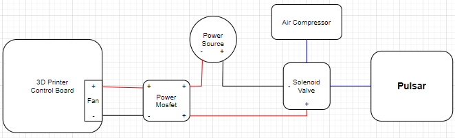
# Using the cooling shroud with your printer board
If you want your 3d printer board to control the air supply, you will have to use a solenoid valve with a power mosfet and plug the relay signal in the FAN input of your 3d printer controller board.
Please refer to the following diagram for connecting the cooling shroud:
# Pellets Feeding
# Automated Pellets Feeding
The Pulsar™ is compatible with our automated pellets feeding system. Please check our pellets feeding system (opens new window) section for more details.
# Gravity Feeding
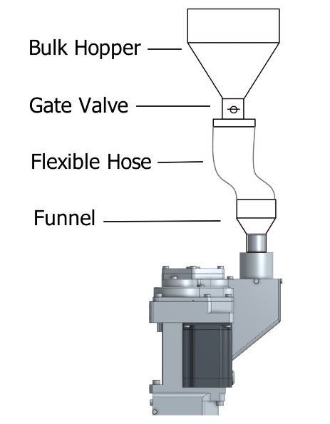
Pellets can also be fed by gravity using some kind of hopper. We do not have a hopper design to suggest as there's no universal solutions. However, our recommendations would be the following :
- Have a bulk hopper placed above the 3D printer or robotic arm with a cone converging into the outlet with an angle between 60-120° locked with a gate valve or actuated door
- Install a small funnel onto the tube.
- Link the funnel to the Bulk Hopper outlet using a flexible hose. Make sure the hose's length can reach the far corners of the print area.
- Use the sensor on the Pulsar to control the door's opening
To prevent bridging in the hose, the funnel will allow you to increase the hose inside diameter above 1". The Pulsar inlet is 3/4" to balance the airflow required when in an air powered conveyor setup relative to the quantity of material.
# 3D Printer Guideline
The Pulsar™ is a lot longer to most extruder for FDM applications. It is imperative you follow the following guidelines to ensure a safe approach to limit potential damages to your Pulsar™ extruder & printer.
# Ideal Pellets
With the following features, you will achieve the best conveying and feeding results. The current design of the Extrusion screw is optimised for the following :
- Spherical
- 3-5 mm in diameter
- Minimal size variation
# Other Pellets
It’s possible to use other pellets. Results will vary. Below is a summary of what to expect.
| Pellet Type | Air Conveying | Feeding | Extrusion Flow | Note |
|---|---|---|---|---|
| Sphere | Great | Great | Great | Ideal format |
| Repro (Flat disk) | Fair | Good | Great | Good format |
| Cylinder (2.85 mm chopped) | Good | Fair | Good | Ok |
| Cylinder (1.75 mm chopped) | Fair | Bad | Bad | Not ideal, Mix with better format |
| Flakes | Bad | Bad | Fair | Not ideal, Mix with better format |
| Powder | Bad | Incompatible | Incompatible | Incompatible |
# What to expect with
# Repro
Repro consists of flat disks usually 3-5 mm in diameter with a thickness of around 1.5-2 mm.
Common issues :
Air Conveying : some disks may fly out or wedge through the air exhaust slots of the inlet tube. It may restrict the airflow so that conveying loses efficiency
Suggested Fix :
- Add a cylinder screen to reduce the chance of a blockage inside the Inlet Tube
- Attach a custom hopper on the Inlet Tube to match your material size
Feeding : Due to their shape, some disks may wedge and shear where the Extrusion Screw feeds the material through the throat of the housing. Noisier operation is to be expected. In some cases, maximum extrusion flow can be slightly affected.
Suggested Fix :
- Reduce max output flow by 5-15%
# Cylinder (2.85mm Chopped)
It is common to see 2.85 mm filament recycled in pellet shape.
Common issues :
Air Conveying : The sharp edges of the chopped filament can build up in bridges in the air hoses.
Suggested Fix :
- Increase hoses and venturi diameter.
- Increase conveying pressure
- Add agitation in the bulk hopper leading to the venturi
Feeding : Due to their shape, some cylinders may wedge and shear where the Extrusion Screw feeds the material through the throat of the housing. Noisier operation is to be expected. In some cases, maximum extrusion flow can be affected.
Suggested Fix :
- Reduce max output flow by 15-25%
- Dilute bulk with spherical pellets
Extrusion Flow : Irregular flow can happen with heavy trouble in the feeding section. It is easily noticeable when the motor starts skipping steps
Suggested Fix :
- Increase stepper motor voltage (Max. 48V)
- Dilute bulk with spherical pellets
- Change Feeding philosophy from flood to starve
# Flakes
It is common to see flakes as a means to recycle material. Shredded flakes or formed flakes will have similar results. Consider using a pelletizer to reshape the plastic in spheres.
Common issues :
Air Conveying : The sharp edges of the flakes will bridge in a small hose
Suggested Fix :
- Increase hoses and venturi diameter.
- Increase conveying pressure
- Add agitation in the bulk hopper leading to the venturi
- Dilute with spherical pellets
Feeding : Due to their shape, some flakes may wedge and shear where the Extrusion Screw feeds the material through the throat of the housing. Noisier operation is to be expected. In some cases, maximum extrusion flow can be affected. Due to the steep maximum angle of repose of flakes, automatic feeding may be erratic.
Suggested Fix :
- Reduce max output flow by 25-50% -Dilute bulk with spherical pellets
Extrusion Flow : Should the previous issues be serious enough, inconsistent flow is to be expected.
Suggested Fix :
- Dilute bulk with spherical pellets
# Powder
Powder is incompatible with the Pulsar Extruder.
# Retraction
While in operation, the screw of the pellet extruder must turn exclusively counterclockwise. Retraction must not be used. Turning the screw clockwise will lift melted material in unwanted zones where it can clog the flow. There’s an anti-oozing feature that will prevent oozing from happening.
# General
Printing without cooling is only possible with large parts. Thick and large layers take time to cool down, thus requiring you to reduce speed for small parts.
Z homing must be done very carefully due to thermal expansion. For bed leveling with a cold extruder, make sure you compensate the thermal expansion:
- 0.32mm @ 200°C
- 0.49mm @ 300°C
- 0.66mm @ 400°C
# Use Z lift
Raising the Z axis between each fast-travel is required. It will prevent any collision with the printed part. See the Slicer section for more info.
# Consider thermal expansion
It’s critical to consider the heat cylinder thermal expansion when doing the bed leveling. For example, if leveling at room temperature, the printing head will be 0.25mm lower. See the General topic to learn more.
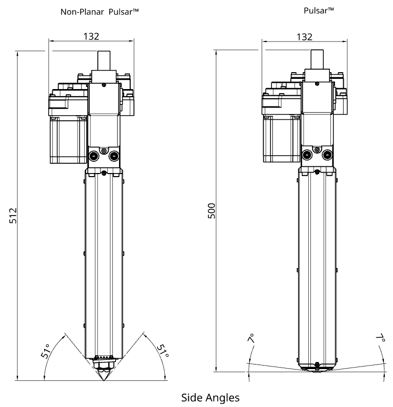
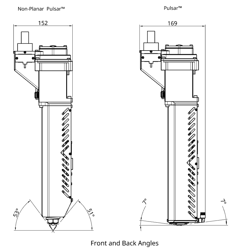
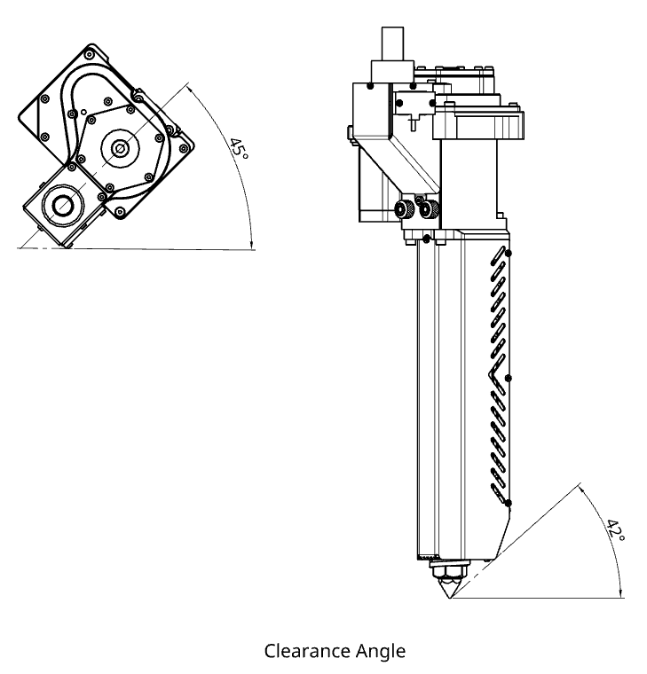
# Non-Planar Pulsar™
The guidelines described in this document regarding the Pulsar™ also apply to the Non-Planar Pulsar™. There is no extra wiring, electronics or mounting to do.
Refer to the drawings and table below for an overall comparison between the Pulsar™ and Non-Planar Pulsar™.
| Pulsar™ | Non-Planar Pulsar™ | |
|---|---|---|
| Maximum recommended nozzle temperature | 500 °C | 400 °C |
| Overall height | 500 mm | 512mm |
| Part cooling | ✅ | ❌ |
| Minimal inclination angle (refer to drawings below) | 7 ° | 42 ° |
Due to the gravity having a major impact on the pellets’ flow, the Non-Planar Pulsar™ has a reduced flow rate when inclined. The following table gives an approximation of the expected percentage of flow rate in function of the backwards/forwards angle and side angle. Overall, the following recommendations are to be considered if the Non-Planar Pulsar™ is to be inclined:
- Avoid forwards inclinations
- Prioritize backwards angles when possible
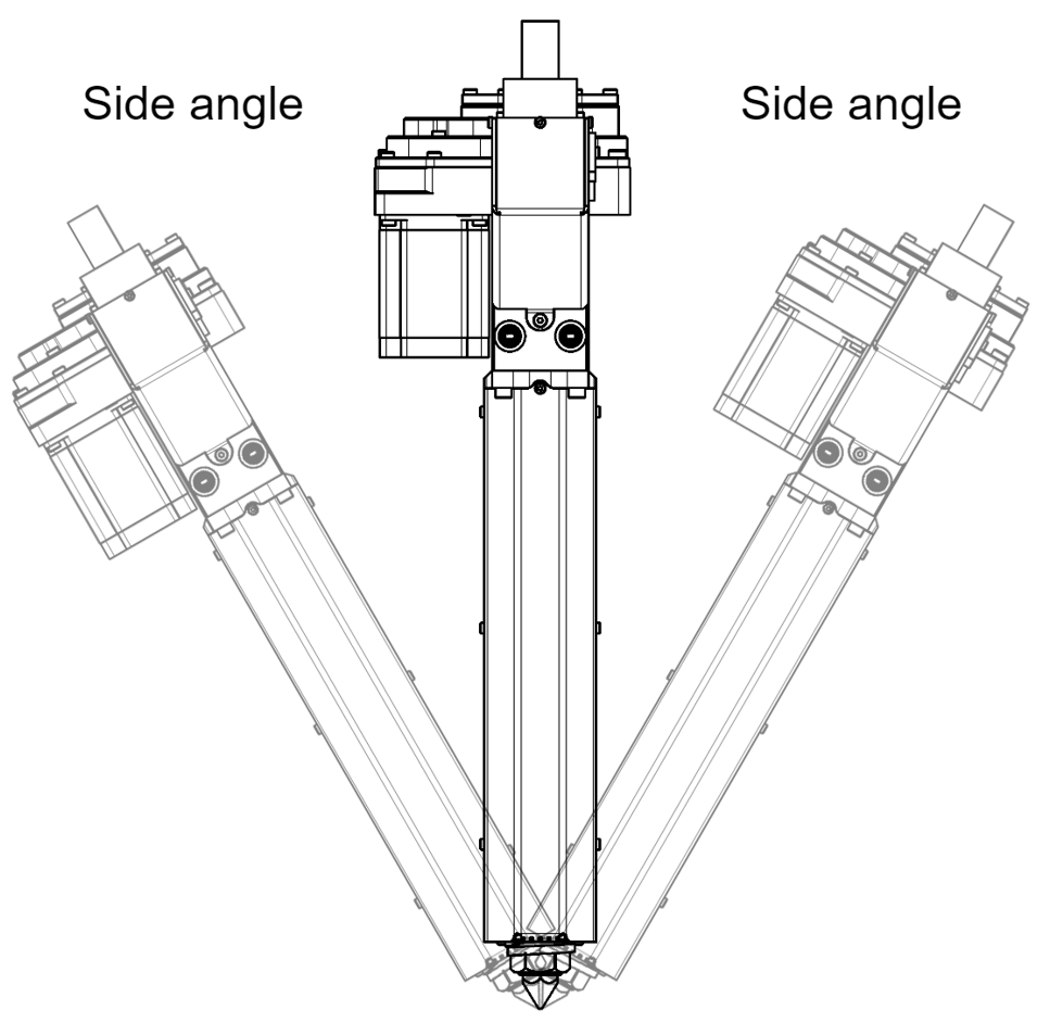
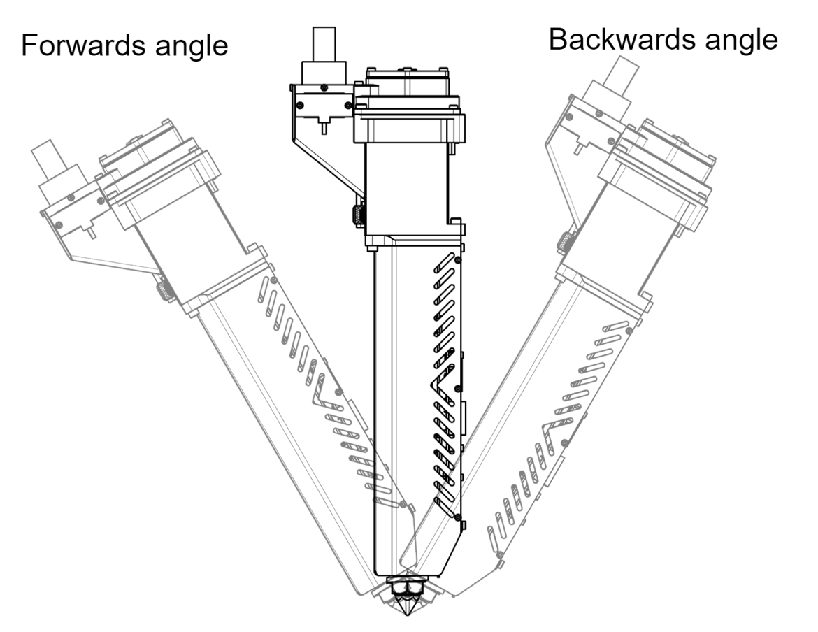
| Forwards angle | Backwards angle | ||||||
|---|---|---|---|---|---|---|---|
| Side angle | -45° | -30° | -15° | 0° | 15° | 30° | 45° |
| 0° | 0% | 47% | 72% | 100% | 100% | 100% | 100% |
| 15° | 0% | 38% | 58% | 80% | 89% | 90% | 92% |
| 30° | 0% | 34% | 51% | 71% | 80% | 80% | 84% |
| 45° | 0% | 27% | 42% | 57% | 60% | 63% | 75% |
WARNING
Hot nozzle. Beware, contact may cause burns.
# Robotic Arm Guideline
If you plan on installing the Pulsar™ on a robotic Arm, you'll need to get some extra hardware to get the same features as a 3D printer controller. These items are the following:
- A motion planner capable of outputting STEP / DIR pulses for the stepper driver.
- Three (3) temperature controllers capable of working with PT100 temperature sensors. Their output will drive a SSR.
# Firmware
# Marlin Firmware
2.0.x# Configuration.h
Set number of extruders:
#define EXTRUDERS 3
Set the correct temperature sensor values. Please refer to Marlin thermal settings (opens new window) to find the correct value based on your amplifier circuit or your actual setup.
#define TEMP_SENSOR_0 68 //could also be 20 or 21. Check the Marlin thermal settings.
#define TEMP_SENSOR_1 68 //could also be 20 or 21. Check the Marlin thermal settings.
#define TEMP_SENSOR_2 68 //could also be 20 or 21. Check the Marlin thermal settings.
Set temperature min temp:
#define HEATER_0_MINTEMP 19
#define HEATER_1_MINTEMP 19
#define HEATER_2_MINTEMP 19
Set temperature max temp:
#define HEATER_0_MAXTEMP 485
#define HEATER_1_MAXTEMP 485
#define HEATER_2_MAXTEMP 485
The heaters are very powerful, which is required for engineering and advanced polymers. If you are planning on printing low temperature, reduce the bang_max from 255 to 127.
Set temperature bang_max:
#define BANG_MAX 127
Increase the PID_functional_range:
#define PID_FUNCTIONAL_RANGE 100
Set the base PID values:
 #define DEFAULT_Kp 23.1
 #define DEFAULT_Ki 0.039
 #define DEFAULT_Kd 157.8
WARNING
Please perform a PID autotune for each heating element. Values may vary depending on the heater’s environment.
Set the extruder steps per mm:
#define DEFAULT_AXIS_STEPS_PER_UNIT { XXX.XX, XXX.XX, XXX.XX, 224.6 }
Note: {X Axis, Y Axis, Z Axis, E Axis} The value of the XYZ axis may vary and are shown as XXX.XX
Set the max feed rate:
#define DEFAULT_MAX_FEEDRATE { XXX, XXX, XXX, 150 }
Note: {X Axis, Y Axis, Z Axis, E Axis} The value of the XYZ axis may vary and are shown as XXX.XX
INFO
The feed rate is capped at 150 mm/s. Although the Pulsar isn’t fed a filament, we use a combination of a step/mm coupled with a configuration on slicers (see slicer section) to convert the RPM of the extruder into mm/s.
The following equation gives the RPM of the motor :

Switch enable logic for the extruder motor:
#define E_ENABLE_ON 1
# Configuration_adv.h
Configure the external stepper driver
#define MINIMUM_STEPPER_POST_DIR_DELAY 500
#define MINIMUM_STEPPER_PRE_DIR_DELAY 500
#define MINIMUM_STEPPER_PULSE 3
#define MAXIMUM_STEPPER_RATE 200000
# RepRap Firmware
TIP
In your configuration file, you should find values similar to the ones below. However, we do recommend that you use the online ReRap Firmware configurator tool (opens new window).
WARNING
The following information is based on Duet 2 and RepRap Firmware 3.x. We strongly suggest that you also read the official Duet/RepRap documentation (opens new window) to make sure you correctly connected and configured your Duet board, pt100 (RTD) amplifier board and RepRap firmware version.
# Config.g
Set the correct temperature sensor values. Please refer to Duet documentation to find the correct value based on your amplifier circuit.
TIP
For the Duet 3 MB6HC, pins spi.cs1 to spi.cs3 should be replaced with spi.cs0 to spi.cs2.
M308 S1 P"spi.cs1" Y"rtd-max31865"    		   ; configure sensor 1 as PT100 connected to RTD1 on lower daughter board
M308 S2 P"spi.cs2" Y"rtd-max31865"             ; configure sensor 2 as PT100 connected to RTD2 on lower daughter board
M308 S3 P"spi.cs3" Y"rtd-max31865"             ; configure sensor 3 as PT100 connected to RTD1 on upper daughter board
Set temperature max temp:
M143 H0 S480
M143 H1 S480
M143 H2 S480
Set the extruder steps per mm:
M92 XXXX.X YXXX.X ZXXX.X E224.6
Set the max feed rate:
M203 XXXXX YXXXX ZXXXX E9000
INFO
The feed rate is capped at 9000 mm/min. Although the Pulsar isn’t fed a filament, we use a combination of a step/mm coupled with a configuration on slicers (see slicer section) to convert the RPM of the extruder into mm/s.
The following equation gives the RPM of the motor :

Assign heaters 1, 2 and 3 to the same tool:
M563 P0 D0 H1:2:3 S"Pulsar"
Start with the following values for the PID tuning:
M307 H1 A940 C810 D22 S1.0 B0
M307 H2 A940 C810 D22 S1.0 B0
M307 H6 A795 C920 D10 S1.0 B0
INFO
These values must be adjusted based on your application because parameters such as the printing temperature, environment and cooling unit will change the results.
If the values are unstable (oscillation > +-2°C), a new PID tuning is required.
Follow the firmware recommendation for tuning. Start from the top heater, then the middle heater and finally the bottom heater, one at the time.
If after a tuning you still have a lot of overshoot (>25°C), you can evaluate reducing the "S1.0" From the M307 command to a lower value. Please note that reducing the maximum heater power (Having an S value lower than 1.0) can also reduce the maximum reachable flow.
Configure external stepper drivers:
M569 PXXX SXXX R1 T3:3:5:0
# Repetier Firmware
TIP
In your configuration file, you should find values similar to the ones below. However, we do recommend that you use the online Repetier Firmware configurator tool (opens new window).
# Configuration.h
Set the correct temperature sensor values. Please refer to Repetier configurator tool (opens new window) to find the correct value based on your PT100 amplifier circuit.
#define EXT0_TEMPSENSOR_TYPE 13
#define EXT1_TEMPSENSOR_TYPE 13
#define EXT2_TEMPSENSOR_TYPE 13
Set minimum temperature:
#define MIN_DEFECT_TEMPERATURE 20
Set maximum temperature:
#define MAXTEMP 500
#define MAX_DEFECT_TEMPERATURE 505
The heaters are very powerful, which is required for engineering and advanced polymers. If you are planning on printing low temperature, reduce the bang_max from 255 to 127.
Set maximum power output:
#define EXT0_PID_MAX 127
#define EXT1_PID_MAX 127
#define EXT2_PID_MAX 127
Set the extruder steps per mm:
#define EXT0_STEPS_PER_MM 224.6
Set the max feed rate:
#define EXT0_MAX_FEEDRATE 150
INFO
The feed rate is capped at 150 mm/s. Although the Pulsar isn’t fed a filament, we use a combination of a step/mm coupled with a configuration on slicers (see slicer section) to convert the RPM of the extruder into mm/s.
The following equation gives the RPM of the motor :
Switch enable logic for the extruder motor:
#define EXT0_ENABLE_ON 1
# Configuration_adv.h
Configure the external stepper driver
#define STEPPER_HIGH_DELAY 3
#define DIRECTION_DELAY 5
# Slicer and Print Settings
# Slicer guidelines
Set vertical lift to at least your layer thickness. For layers of 1.00mm, lift 1.00mm. Slicers aren’t yet optimized for large prints. Many over-extruded sections will be noticeable. Lifting the head will prevent any collision with the printed part.
Wipe nozzle to at least the line width. For a line width of 3.50mm, wipe 3.50mm or greater.
Set the heating to all heaters to the required temperature.
Set end script to turn off the three heaters in the extruder:
M104 T0 S0 ; turn off extruder
M104 T1 S0 ; turn off extruder
M104 T2 S0 ; turn off extruder
Output flow and pressure greatly changed depending on the printing speed. To get the best result, keep the output flow steady by keeping the same speed everywhere.
Change the filament setting to 2.85 mm. The Pulsar’s step/mm was calculated using the area of a 2.85 mm filament. You will notice an exaggerated over extrusion with 1.75 mm filament in the slicer’s settings.
Never use retraction with the Pulsar. The pressure generating screw cannot work in the opposite direction.
The theoretical maximum speed for the screw is 60 RPM. This speed is for an empty screw. Filled with polymer, maximum RPM should be below 50 RPM.
# Recommended Flow Rate (g/hr)
| Material | Upper Barrel Temp (°C) | Lower Barrel Temp (°C) | Nozzle Temp (°C) | 5 mm | 3 mm | 1 mm |
|---|---|---|---|---|---|---|
| HDPE | 180 | 220 | 220 | 2159 | ||
| TPE | 170 | 180 | 180 | 2054 | ||
| PLA 3D850 | 200 | 200 | 200 | 2581 | ||
| PLA 4043D | 200 | 200 | 200 | 2559 | ||
| PLA 3D700 | 200 | 200 | 200 | 3018 | ||
| PLA 3D700 | 190 | 190 | 190 | 2779 | 1731 | |
| rPETG | 150 | 230 | 230 | 2653 | ||
| PP | 150 | 230 | 230 | 1985 | ||
| ABS | 200 | 230 | 230 | 2099 | ||
| NA6 | 220 | 255 | 255 | 1639 | ||
| NA6CF | 220 | 255 | 255 | 1600 | ||
| PC | 250 | 290 | 290 | 2479 |
# Absolute Maximum Flow Rate (g/hr)
| Material | Upper Barrel Temp (°C) | Lower Barrel Temp (°C) | Nozzle Temp (°C) | 5 mm | 3 mm | 1 mm |
|---|---|---|---|---|---|---|
| HDPE | 180 | 220 | 220 | 2399 | ||
| TPE | 170 | 180 | 180 | 2282 | ||
| PLA 3D850 | 200 | 200 | 200 | 2868 | ||
| PLA 4043D | 200 | 200 | 200 | 2843 | ||
| PLA 3D700 | 200 | 200 | 200 | 3354 | ||
| PLA 3D700 | 190 | 190 | 190 | 3088 | 1923 | |
| rPETG | 150 | 230 | 230 | 2948 | ||
| PP | 150 | 230 | 230 | 2205 | ||
| ABS | 200 | 230 | 230 | 2332 | ||
| NA6 | 220 | 255 | 255 | 1821 | ||
| NA6CF | 220 | 255 | 255 | 1778 | ||
| PC | 250 | 290 | 290 | 2755 |
# Flow to RPM
For some applications, such as robotic arms, it's easier to configure the motor RPM rather than using the length of material to extrude, as seen in traditional 3D printer controllers. The following table lists the parameters for the F-RPM factor, which is the Flow to RPM variable discussed in our blog post here. (opens new window)
| Polymer | Detailed | Top Heater | Bottom Heater | Nozzle Heater | Flow-to-RPM Ratio | Max flow (mm^3/s) |
|---|---|---|---|---|---|---|
| Modified PESU / Carbon Fiber | Airtech Dahltram U-350CF | 400 | 400 | 400 | 0.45 | 702 |
| Modified PEI / Carbon Fiber | Airtech Dahltram I-350CF | 400 | 400 | 400 | 0.54 | 971 |
| Modified ABS / Carbon Fiber | Airtech Dahltram S-150CF | 240 | 240 | 240 | 0.64 | 658 |
| Modified PC / Carbon Fiber | Airtech Dahltram C-250CF | 300 | 300 | 300 | 0.55 | 728 |
| Modified PC / Glass Fiber | Airtech Dahltram C-250GF | 320 | 320 | 320 | 0.44 | 640 |
| PETG | Fortis 3D PETG | 260 | 260 | 260 | 0.7 | 592 |
| PLA | Ingeo 3D850 | 200 | 200 | 200 | 0.61 | 607 |
| PLA | Ingeo 3D700 | 0 | 190 | 190 | 0.58 | 560 |
| Nylon 6 | Fortis 3D PA6 | 240 | 240 | 240 | 0.68 | 627 |
| HDPE | HDPE | 180 | 217 | 220 | 0.73 | 1373 |
| HDPE | HDPE | 180 | 220 | 220 | 0.98 | 406 |
| Nylon 66 / Glass Fiber | PA 6/6 13% GF | 300 | 300 | 300 | 1.05 | 503 |
| PC | PC | 310 | 310 | 310 | 0.58 | 633 |
| PC | Chase Plastics PC | 250 | 250 | 250 | 0.5 | 360 |
| PMMA | PMMA | 245 | 240 | 240 | 0.77 | 542 |
| TPV | TPV | 220 | 240 | 240 | 0.65 | 1006 |
| PEEK / Carbon Fiber | PEEK 30% CF | 380 | 380 | 380 | 0.63 | 516 |
| Modified PP | PP X-21084-M ECC | 170 | 200 | 200 | 0.74 | 440 |
| TPE | TPE | 180 | 180 | 180 | 0.61 | 671 |
# Nozzle size
The Pulsar can be offered with different nozzle sizes. The table below provides a general idea of the effect of the nozzle size on the F-RPM factor. Smaller nozzles increase pressure, thus the screw needs to rotate more to extrude material.
| Polymer | 5.00mm | 4.00mm | 3.00mm | 2.00mm | 1.00mm |
|---|---|---|---|---|---|
| PLA 3D850 | 100% | 135% | 153% | 171% | 205% |
| TPE | 100% | 104% | 107% | 100% | 114% |
| PC | 100% | - | - | 144% | 174% |
| PP | 100% | 104% | 91% | 95% | 105% |
| PA6 | 100% | 128% | 150% | 211% | 274% |
Smaller nozzles make it harder to achieve high throughput. The table below lists a general rule of thumb for the effect of nozzle size on maximum flow compared to the 5.00mm nozzle reference. Results may vary depending on the resin, additive, and reinforcements.
| Polymer | 5.00mm | 4.00mm | 3.00mm | 2.00mm | 1.00mm |
|---|---|---|---|---|---|
| Any | 0 | -60mm^3/s | -120mm^3/s | -180mm^3/s | -240mm^3/s |
# Screw Type
The Pulsar can be offered with four different types of screws, each with its own compression ratio. Unless noted, the Pulsar comes with a "Standard Screw" (ST). The following screws are also available:
- Minimal Compression (MC)
- Low Compression (LC)
- High Compression (HC)
The table below lists a general rule of thumb for the effect of the screw type on maximum flow for some polymers:
| MC | LC | ST | HC | |
|---|---|---|---|---|
| PETG | 111% | 38% | 100% | - |
| PLA 3D850 | 107% | 89% | 100% | 85% |
| PA6 | - | - | 100% | 169% |
As you can see, the High Compression screw (HC) can be very beneficial for PA polymers. For the best performance, check your resin datasheet and order the appropriate screw.
# Maintenance
# Gears
The gear should be greased through the two greasing ports accessible from top. Let the motor run freely while gently applying grease.
We suggest using white lithium grease. The Pulsar comes pre-greased with white lithium grease, ISO Viscosity Grade of 150.
We suggest using a small sized grease gun such as the Astro Mini Grease Gun.
# Bearings
The roller bearing needs to be periodically greased. To do so, it requires removing the top cover. The bearing is in two parts. Apply grease on the outer race & re-assemble the top cover. Between 5 - 10 grams of grease is enough.
See below chart for bearing greasing frequency :
| Operating temperature (°C) | Grease frequency (hr) |
|---|---|
| < 50 | 2500 |
| 50 < OT < 80 | 1250 |
| 80 < OT | 450 |
# Periodic Inspection
To ensure longetivity of the gearbox and it's components, periodic in depth inspection and maintenance is suggested.
# Gearbox Maintenance & Inspection
Inspect all the gears and housing periodically. To do so, remove the top cover and clean all the grease.
Gears with excessive wear marks or worn down teeth should be replaced.
# Extrusion Screw Maintenance & Inspection
Inspect the extrusion screw periodically. Follow the procedure Removing the Extrusion Screw to get a good look at this critical machine element. Even under normal use condition, this machine element is heavily solicitated. This element has a finite lifecycle of approximately 10 000 hours. Discoloration and burn marks are not serious damage event. Burnt material should be cleaned to improve extrudate quality.
Consider replacing the extrusion screw if your extrusion screw has the following defect :
- Flight width below 1 mm
- Severely damaged mating feature with Gearbox. Replace the matching gear and bearings.
- Severely corroded Extrusion screw. Holes and oxidation marks can appear. See Purging the Pulsar to protect the Extrusion Screw from chemical attack during down time
- Cracks or damage in the root diameter or flight
# Purging the Pulsar
Purging Compound consists of inert material used to clean the Extruder.
General purpose is used in low temperature applications to switch between resins, remove corrosive materials for regular downtime & lightly clean the extrusion screw & barrel.
High temperature is used to clean and flush out engineering material. It’s also useful as a step up to engineering material from low temperature resins or step down from engineering material.
Heavy Scrubbing is used for a deep clean of the extruder. It’s useful to flush burnt or carbonized material to an extent. This needs to be paired with a common purge afterwards.
How to Purge
- Empty the Pulsar’s Hopper
- Flush the Barrel using the extrusion command
- Fill your bulk hopper with 250-500 grams of purge
- Bring the Pulsar’s to purging temperature (Warning : make sure it’s compatible with the previous resins temperature range)
- Extrude until there’s no previous material mixed in the purge
- Increase the extrusion rate to the maximum without steps skipping
- Purge for 180 - 300 grams of purging compound
Extra Steps for material or Purge change
- Empty the bulk and Pulsar’s hopper
- Flush the Barrel using the extrusion command
- Fill the Bulk hopper with new material
- Bring the Pulsar to set temperature (Warning : make sure it’s compatible with the previous resins temperature range)
- Extrude until there’s no previous material mixed
# Swap Nozzle
Swap Nozzle Detailled Procedure (opens new window)
WARNING
There’s some disassembly required to change the nozzle on the Pulsar™ extruder. It requires proximity to high voltage components. Security measure must be put in place and followed rigorously to perform the following actions.
# Tools required
- 2 mm Allen Drive
- 2.5 mm Allen Drive
- 17 mm Hexagonal socket
- Torque Wrench
- Heat the nozzle heater close to your resin melt temperature and cut the main power
- Unscrew the M03 and the two M04 & remove the Bottom Bracket
- Remove the nozzle (factory assembled to 32.5 N*m)
- Replace the nozzle and tighten to 32.5 N*m to ensure proper sealing
- Replace bottom bracket & Calibrate Z height
# Dismount the Heatcore
This procedure is to remove the Pulsar™ Heatcore. The extrusion screw will come with the Heatcore
Dismount the Heatcore Detailled Procedure (opens new window)
# Tools required
- Shop Vacuum
- 3 mm Allen Key
- 7 mm Allen Key
- Unplug all the connectors on the backplate
- Vacuum the excess of material in the hopper
- Unscrew the M10 screw
- Unscrew the four M5 screw
- Pull on the Heatcore and set aside
# Removing the Extrusion Screw
WARNING
This procedure requires deep knowledge of the extruder. Make sure you read and understand the procedure before any attemp at dissassembly is performed.
WARNING
There’s some disassembly required to dissassemble the Pulsar™ extruder. It requires proximity to high voltage components and extremely hot components. Security measure must be put in place and followed rigorously to perform the following actions.
Removing the Extrusion Screw Detailled Procedure (opens new window)
# Tools required
- Shop Vacuum
- 2.5 mm Allen Key
- 3 mm Allen Key
- 7 mm Allen Key
- Wrench 16 mm
# Dehumidifying Maintenance Routine
Diagnosing the Problem
To diagnose the insulation, use a multimeter set to 200MΩ. Measure the resistance between one of the heater's power cables and the ground. A healthy reading should be above 1MΩ or show an "Open Circuit" reading.
If you get a low resistance reading, it's most likely due to moisture. This is a common issue that you can resolve by gently drying the heater.operating temperature.
The Drying Process
Follow these steps to safely remove moisture from the heater:
Turn on the printer and set the hot end temperature to 50-75°C. The goal is a gentle, sustained warmth. Maintain this temperature for at least 2 hours to allow the moisture time to fully evaporate.
Next, increase the hot end temperature to 95°C and hold it there for at least 2 more hours.
Use your multimeter to check the resistance again. When the multimeter shows an "open circuit" or "OL" reading, the heater is dry.
Once the heater is dry, you can safely run it at its normal operating temperature.