# Hotends DyzEnd-X DyzEnd Pro
# Assembly
Insert the heater cartridge in the heater block.
Tighten the screw: Tighten the M3 flat heat screw using a 2mm Hex. Do not over-tighten. Hold the hotend by the heatblock to avoid bending the heatbreak.
Add the thermistor: Tighten the temperature sensor in the heater block. Hold the hotend by the heatblock to avoid bending the heatbreak.
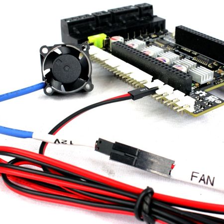
Add the cable tie: Group every cable from the heater cartridge, the temperature sensor and the fan using a cable tie.
WARNING
The sensor can be damaged if not grouped with other cables.
# Nozzle tightening torque
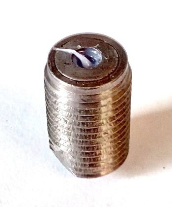
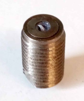
The nozzle should be tighneted to 4Nm.
Put the sealing washer inside the pocket on the top of the nozzle. Make sure the small diameter is toward the outside of the nozzle. Keep the nozzle as vertical as possible. Tighten the nozzle inside the heatblock with you fingers.
# Setup for Bowden
The DyzEnd can work either way, in direct drive using the groove mount system or in Bowden setup using an adapter. Make sure you get both the hotend and the Bowden adapter when you place your order.
- For the hotend alone, you need a length of 22mm, from the top of the groove mount system.
- Add the height of your fitting.
- Mark the tubing to visualize the depth.
- Insert the tubing up to the mark. The filament must be well guided inside the hotend with this tubing.
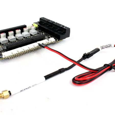
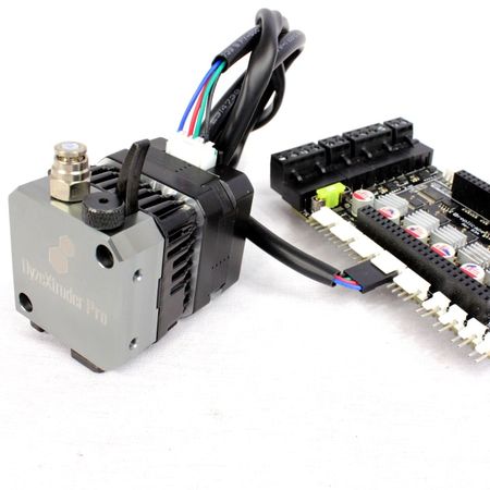
# Electronics wiring
Look for the right place to connect the hotend to your main board. You may need to check with your board manufacturer to get a connection drawing.
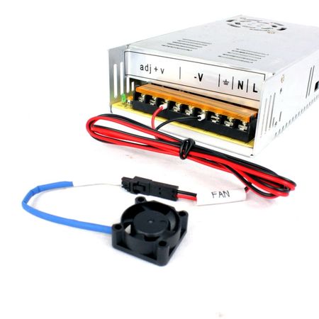
# Fan connection
Directly to your Power Supply V+ and V-. Must be ON all time. Some board have built-in fan output, make sure the voltage is according to your hotend.
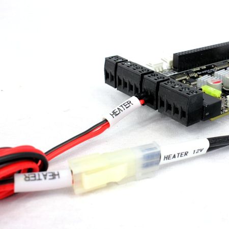
# Heater connection
Hotend heater output: E0, E1, E2, …
INFO
Please note that there is no polarity on the heater.
# Thermistor connection
Temperature input: T0, T1, T2, …
# Motor connection
Extruder Stepper: E0, E1, E2, …
# Firmware Configuration
If you have a hard time trying to configure your firmware, do not hesitate to contact us (opens new window) ! We will be more than happy to help you!
# Marlin Firmware
1.1.0 RC7+# 300 °C Thermistor White heatshrink
# Configuration.h modification
Depending on your number of hotends, you can modify only the corresponding heater number to get our DyzEnd to work.
Find these lines and modify these values:
#define TEMP_SENSOR_0 3
#define TEMP_SENSOR_1 3
#define TEMP_SENSOR_2 3
#define HEATER_0_MINTEMP 0
#define HEATER_1_MINTEMP 0
#define HEATER_2_MINTEMP 0
#define HEATER_0_MAXTEMP 300
#define HEATER_1_MAXTEMP 300
#define HEATER_2_MAXTEMP 300
// DyzEnd
#define DEFAULT_Kp 19.3
#define DEFAULT_Ki 2.1
#define DEFAULT_Kd 44.6
# 500 °C Thermistor Black heatshrink
Use the latest Marlin Firmware
Marlin Firmware (opens new window) is updated with Dyze Design compatibility since version 1.1.0 RC7. Updating your firmware to the latest version will have beneficial results with print quality.
# Configuration.h modification
Depending on your number of hotends, you can modify only the corresponding heater number to get our DyzEnd to work.
Find these lines and modify the values:
#define TEMP_SENSOR_0 66
#define TEMP_SENSOR_1 66
#define TEMP_SENSOR_2 66
#define HEATER_0_MINTEMP 21
#define HEATER_1_MINTEMP 21
#define HEATER_2_MINTEMP 21
#define HEATER_0_MAXTEMP 500
#define HEATER_1_MAXTEMP 500
#define HEATER_2_MAXTEMP 500
// DyzEnd
#define DEFAULT_Kp 14.0
#define DEFAULT_Ki 0.5
#define DEFAULT_Kd 125.0
# Configuration_adv.h modification
#define MAX_CONSECUTIVE_LOW_TEMPERATURE_ERROR_ALLOWED 5
#define MILLISECONDS_PREHEAT_TIME 30000
# Repetier Firmware
# 300 °C Thermistor White heatshrink
# Configuration.h modification
Find the following parameters and replace the values:
#define DECOUPLING_TEST_MAX_HOLD_VARIANCE 60
#define DECOUPLING_TEST_MIN_TEMP_RISE 1
#define EXT0_TEMPSENSOR_TYPE 3
#define EXT0_DECOUPLE_TEST_PERIOD 90000
#define MAXTEMP 300
#define MIN_DEFECT_TEMPERATURE 0
#define MAX_DEFECT_TEMPERATURE 300
Please note that you may not find the parameters starting with DECOUPLING_TEST if you use an old firmware version.
# 500 °C Thermistor Black heatshrink
Use the latest Repetier Firmware
Repetier Firmware (opens new window) is updated with Dyze Design compatibility on their development branch. Updating your firmware to the latest version will have beneficial results with print quality.
# Configuration.h modification
Find the following parameters and replace the values:
#define DECOUPLING_TEST_MAX_HOLD_VARIANCE 60
#define DECOUPLING_TEST_MIN_TEMP_RISE 1
#define EXT0_TEMPSENSOR_TYPE 15
#define EXT0_DECOUPLE_TEST_PERIOD 90000
#define MAXTEMP 500
#define MIN_DEFECT_TEMPERATURE 21
#define MAX_DEFECT_TEMPERATURE 500
# Smoothie Firmware
# 300 °C Thermistor White heatshrink
# Configuration.h modification
Find the following parameters and replace the values:
#temperature_control.hotend.thermistor EPCOS100K
temperature_control.hotend.rt_curve 25,98640,150,1632,300,106.4
temperature_control.hotend.max_temp 300
# 500 °C Thermistor Black heatshrink
# Configuration.h modification
Find the following parameters and replace the values:
#temperature_control.hotend.thermistor EPCOS100K
temperature_control.hotend.rt_curve         25,4700000,260,2240,500,83.7
temperature_control.hotend.r0               4700000
temperature_control.hotend.max_temp 500
If the temperature stays at 0°C for your hotend using the rt_curve option, you may try to use the Steinhart-Hart curve instead:
temperature_control.hotend.coefficients 0.0005377911415,0.0001693235352,0.00000006894981903
# Redeem Firmware
# 300 °C Thermistor White heatshrink
# Default.cfg file modification
Find the following parameters and replace the values:
temp_chart_E = B57560G104F
max_temp_E = 300
# 500 °C Thermistor Black heatshrink
# Default.cfg file modification
Find the following parameters and replace the values:
temp_chart_E = DYZE500
max_temp_E = 500
# Reprap Firmware
WARNING
Make sure to use Reprap Firmware (opens new window) version 1.17 or later to get the optimal temperature from your thermistor using the Steinhart-Hart coefficients.
WARNING
For RepRapFirmware 3 (RRF3), use M308 (opens new window) and M950 (opens new window) commands. Please refer to their documentation for more details.
# 300 °C Thermistor White heatshrink
# Config.g file modification
Find the following parameters and replace the values:
; Heater and thermistor section
;*** If you have a Duet board with 1K thermistor series resistors, change R4700 to R1000 to the following M305 commands
M305 P1 R4700 H0 L0
M305 P1 T98640 B4632.86 C9.4861662E-08 R4700 H0 L0
# 500 °C Thermistor Black heatshrink
# Config.g file modification
Find the following parameters and replace the values:
;Heater and thermistor section
;*** If you have a Duet board with 1K thermistor series resistors, change R4700 to R1000 to the following M305 commands
M305 P1 R4700 H0 L0
M305 P1 T4606017 B5848 C5.548428e-8 R4700 H0 L0
M307 H1 A580.4 C256.6 D6.4 S0.50		  ; Heating process parameters for 24V a system
M143 S493
# Klipper Firmware
Open the printer.cfg file and locate the [extruder] section.
# 300 °C Thermistor White heatshrink
In the #Extruder section, define a custom thermistor by adding those lines on top of the section and before the [extruder] subsection:
[thermistor Dyze300]
#based on https://docs.dyzedesign.com/general-support/temperature-sensors.html#_300%C2%B0c-thermistor
temperature1: 20
resistance1: 123800
temperature2: 200
resistance2: 550
temperature3: 300
resistance3: 106
In the [extruder] subsection, find and modify:
sensor_type : Dyze300
min_temp: 10
max_temp: 300
# 500 °C Thermistor Black heatshrink
In the #Extruder section, define a custom thermistor by adding those lines on top of the section and before the [extruder] subsection:
[thermistor Dyze500]
#based on https://docs.dyzedesign.com/general-support/temperature-sensors.html#_500%C2%B0c-thermistor
temperature1: 25
resistance1: 4500000
temperature2: 260
resistance2: 2240
temperature3: 460
resistance3: 125.4
In the [extruder] subsection, find and modify:
sensor_type : Dyze500
min_temp: 0
max_temp: 480
# PID tuning and adjustments
PID is what controls the output of your board to your heater element. The PID values we included in the above section are only there as a starting point and are based on a 12V configuration. It is important to run a PID autotune so you can have stable temperature behavior.
Execute PID command
M303 E0 S250 C8INFO
Value
S250of the PID command represent your target printing temperature. You can use any value you want.Adjust the new values into your “configuration.h” file
Reset your EEPROM
Calibrate Z axis
WARNING
The PID tuning is calibrated on a specific temperature, it’s normal to see some instability when trying at higher temperatures.
# Changing your PID values
To change your PID values, you need to update your configuration.h file and flash your firmware as you did in the previous step.
Otherwise, with g-code, it’s really easy and fast to change the PID values for higher temperature printing, like switching from PLA to PEEK. Simply run the M301 command with your PID values.
For example, on our printer, when we want to print PLA at 210°C, we run this g-code:
M301 H1 P15.67 I0.60 D102.06
And when we want to print PEEK at 400°C on the same machine, we run:
M301 H1 P24.67 I1.62 D91.14
# PID Troubleshooting
The first thing we would recommend with the PID Tuning if you have any issues is to increase the functional range. Because our heater cartridge is really fast, the PID functional range might be too slow and cause some overshoot issues.
#define PID_FUNCTIONAL_RANGE 40 /*For example, set to 40 instead of 10*/
# Solution 1 – Reduce the Bang Max value
This solution is recommended if you don’t plan on printing at high temp or you’re comfortable with flashing your firmware each time you want to do higher temperature printing.
For example, on Marlin Firmware, reduce the BANG_MAX value to 200 or even lower.
#define BANG_MAX 255
# Solution 2 – Change the PID default safety range
By default, some firmware defines a low maximum temperature overshoot when doing the PID autotune, which might create some issues with our high-performance heaters. You can change this default behavior with a greater value like 40.
For example, on Marlin, in the PID section of configuration.h add:
#define MAX_OVERSHOOT_PID_AUTOTUNE 40
# Slicer Configuration
Configure your slicer with the following values listed below.
Find the according setting based on your Slicer.
| Parameter | Value Dyzend-X | Value Dyzend Pro |
|---|---|---|
| Retraction distance | 0.50mm – 1.00mm | 0.50mm – 2.00mm |
| Line width | Refer to our printing speed calculator (opens new window) | Refer to our printing speed calculator (opens new window) |
| Printing speed | 1 mm/s – 300 mm/s | 1 mm/s – 300 mm/s |
# About retraction distance
The titanium has a very low thermal conductivity compared to other metals and allows the heatbreak to be very short. The retraction distance must be lower than 1mm. A longer retraction distance will bring the soft plastic in a cold zone and stick to the wall. The cooled plastic cannot be pushed by standard motor and is stuck in place. By keeping the retraction lower than 1mm, the filament stay soft and doesn’t clog in place.
# About Line width
The nozzle has a flat that keeps the extruded plastic flat and even. By extruding larger than twice (2X) the nozzle diameter (which is the flat diameter), the plastic won’t be flattened by the nozzle. It will result in poor finish and blobs. Having a line width smaller than the nozzle will also give poor results. We strongly suggest using 1.5 times the nozzle diameter for standard filaments, and from 1.1 times to 1.25 times the nozzle diameter for hard to extrude filaments ( i.e. Flexible filaments). This will reduce the pressure needed to extrude and give better results.
# About printing speed
Make sure you use the right speed for your nozzle size and layer thickness. You can refer to our product specsheet for detailed output flow based on experimental data.
# Part Cooling
# Fan for part cooling
The dyzend is very sensitive to active cooling on its heatblock and it is very important to guide the airflow toward the part. Avoid any airflow toward the heatblock.
| Fan (mm) | Author | HotEnd | Extruder | Link |
|---|---|---|---|---|
| 40 Axial | DYZE DESIGN | DyzEnd | DyzeXtruder | Thingiverse link (opens new window) |
| 40 Axial | Eriobis | DyzEnd | DyzeXtruder | Thingiverse link (opens new window) |
| 50 Blower | DYZE DESIGN | DyzEnd X / Pro | DyzeXtruder / GT / Pro | Thingiverse link (opens new window) |
# Accessories
Accessories can be mounted on the free side of the DyzeXtruder. This can be very interesting for various situations like auto-bed leveling.
| Setup | Author | HotEnd | Extruder | Link |
|---|---|---|---|---|
| PL-08N Inductive Sensor | Eriobis | DyzEnd | DyzeXtruder | Thingiverse link (opens new window) |
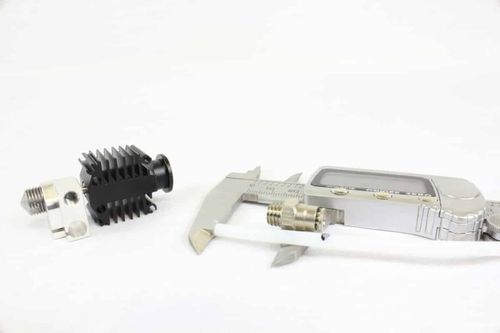
# Liquid cool your hotend DyzEnd-X DyzEnd Pro
Remove the fan
Use a 2mm allen wrench and remove the 4 screws holding the fan.
Apply thermal paste
Apply thermal paste on your heatsink.
Install the liquid cooling block
Use a 2mm allen wrench and install the 4 screws holding the liquid cooling block.
WARNING
Make sure to remove the tape under the liquid cooling block before installing it! Do not over-tighten the screws.
Install the tubing
Install your tubes inside the loop. There is no specific input or output on the liquid cooling block. Do not forget to install the hose clamps if your loop is already completed on the other end.
Crimp the tube clamps
Use a tube crimping plier and crimp the hose clamps.
# Maintenance
# Nozzle Change
WARNING
Do not try to change your nozzle while the hotend is installed. Always remove it from your printer before changing your nozzle.
Nozzle removal
Remove the current nozzle. Use an 8mm wrench for the nozzle and an adjustable wrench for the heat block. Avoid using an adjustable wrench for the nozzle. This tool isn’t optimal and risks damaging the nozzle.If the nozzle seems stuck in the heat block, heat the hotend at half the printing temperature. While sealing, the washer let a little bit of plastic around its perimeter, making it hard to unstuck with certain plastics.
Check if the parts are clean
Check the heat block, the bottom should be clean. Check your nozzle, the sealing washer should be clean. If any of these two parts have plastic on it, make sure to clean them before changing the nozzle to avoid any leaks. Refer to our “Cleaning” section regarding this topic.
New nozzle installation
Put the sealing washer inside the pocket on the top of the nozzle. Make sure the small diameter is toward the outside of the nozzle. Keep the nozzle as vertical as possible. Tighten the nozzle inside the heatblock with you fingers.
Tighten the nozzle
Tighten using a 8mm wrench (DyzEnd-X) 9mm wrench (DyzEnd Pro) with a torque of 4Nm.
WARNING
Make sure to align the heatblock as it was originally before tightening it. Both the sensor cable and the heater cable should be on the fan side.
# Cleaning the hotend
DyzEnd, DyzEnd-X and DyzEnd Pro are very easy to clean and takes only a few minutes.
It is very important to keep the sealing junction clean to avoid any leaks. After each nozzle change, make sure the entire inside is clean. If it is not the case, please follow these few steps to clean it.
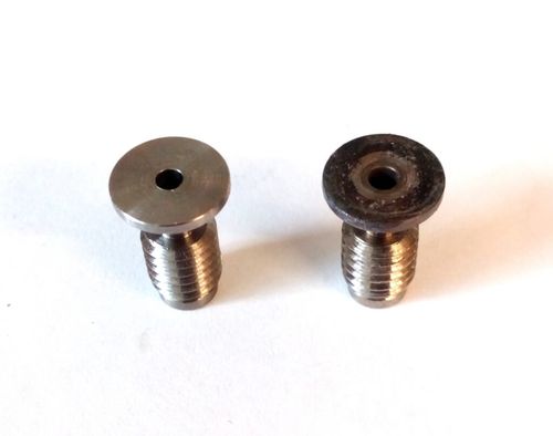
# Cleaning the nozzle
The sealing washer should always stay stuck in place inside the nozzle.
The washer must be clear from plastics. Remove the excess plastic.
WARNING
If you removed the washer while cleaning the nozzle, it is strongly recommended to tighten the nozzle while it is hot for the first time. Hard plastic under the washer will raise it and won’t provide any sealing once melted.
# Cleaning the thermal barrier tube
After you remove your nozzle, take a look at the bottom of the heatblock. If your thermal barrier tube is black and dirty, it will need cleaning.
There are few effective ways to clean it. The surface must be flat and without scratches, make sure to use the proper tools.
Use a fine file
Use an utility knife
Use fine sandpaper
# Troubleshooting
# Filament jammed / Nozzle clogged
This can happen if the nozzle is clogged or if the filament is stuck inside the thermal transition tube. Here are some steps you may follow in order to solve this problem:
# Clean the nozzle orifice
Insert any pin that is sized according to your nozzle, or a little smaller. Needles, wire or small micro-drill can be used. Make sure the plastic inside the hotend is molten. Try to repeat cleaning the nozzle orifice and extruding a few times.
# Momentary increase temperature
There might be impurities, dust or plastic from a previous print that might prevent the nozzle from extruding. By increasing heat, it will be easier to push any debris outside the nozzle. The extruder might be strong enough to push it, or you may need to push the filament by hand.
# Pull what is stuck inside the nozzle
Heat you nozzle at printing temperature and then turn it off. While it is slowly cooling, push filament inside it by hand. Quickly remove the filament and cut the melted part. Put the filament back inside the hotend and repeat. The filament will go deeper inside the nozzle each time, up to the bottom where it will stick to the clogging element.