# Orthus™ Filament Monitor
# Setup and Configuration Overview
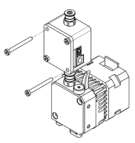
Mount the Orthus on your printer
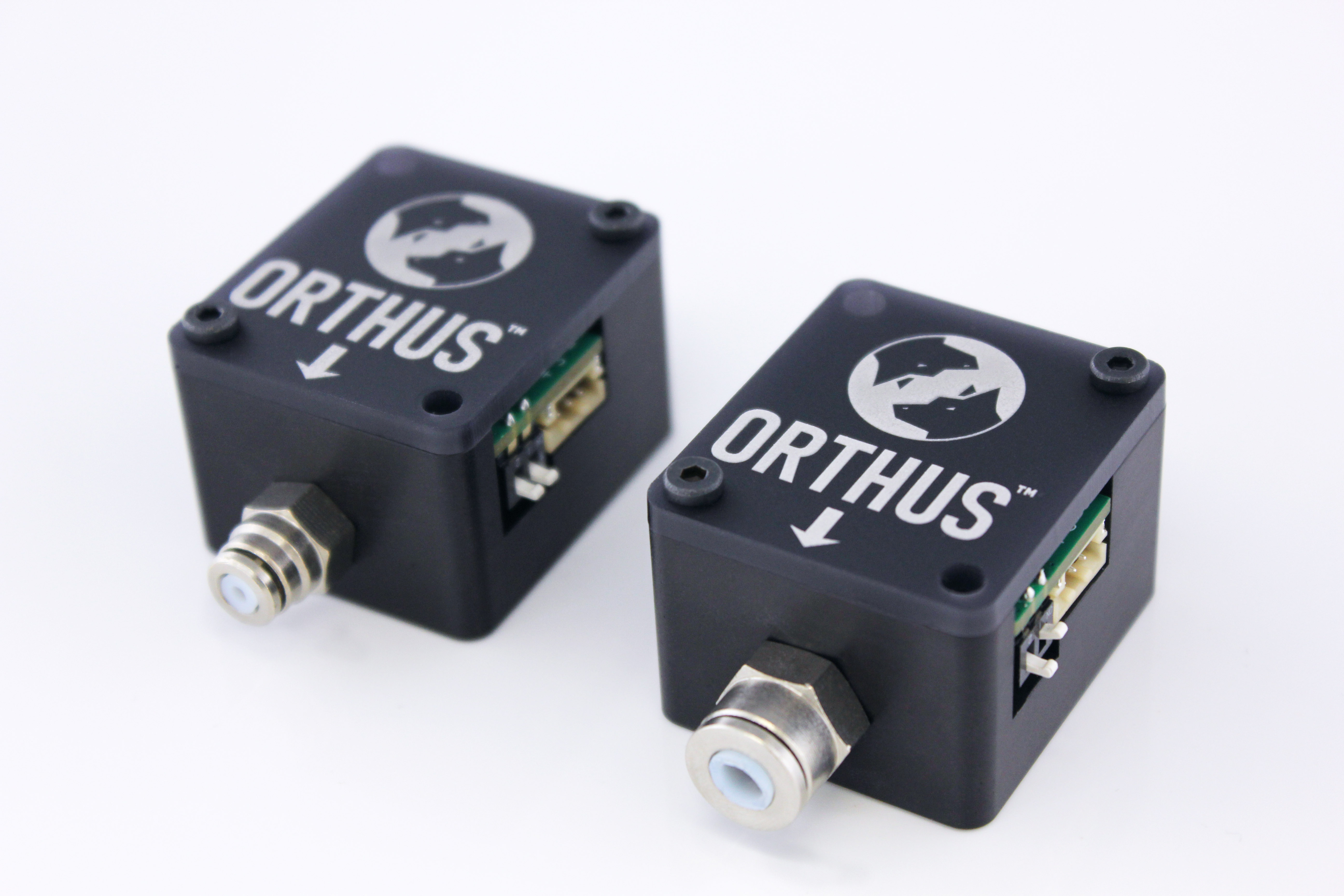
Use the two provided screws to mount the orthus on your printer. The closer the Orthus is to the extruder, the better it will be. Always keep the filament between the Orthus and the extruder fully constrained in tubing. The Orthus should be oriented so that filament is inserted in the direction of the arrow engraved on the acrylic cover.
Please refer to the “Mounting” section of the present guide for further information.
Connect the Orthus to your motherboard
Connect the provided connector to your Orthus. Depending on the motherboard you are using, the pins used will vary.
Refer to the “Wiring” section of the present guide for further information on the pins to use for a specific motherboard.
Configure the firmware
The firmware needs to be configured so that filament monitoring is made possible and that the right version of firmware is installed. The method to do so varies depending on the firmware you are using.
Refer to the “Firmware configuration” section of the present guide to find the procedure associated with your firmware.
Protect your prints!
Your Orthus filament monitor is now installed and ready to use. Whenever a problem will show itself while printing, be it filament blockage, filament break or extruder malfunction, the Orthus will be there to pause the print until the problem is resolved.
# General
# How it works
The Orthus is an extremely precise magnetic filament monitor that outputs a set amount of pulses per millimeter of material running through it.
With this output, it is possible to determine if the extruder is actually pushing the amount of filament that it is supposed to.
The Orthus hence makes it possible to detect if the filament is jammed, cut, or even if the extruder is faulty and not outputting what it should be, no matter the type of filament (hard/soft, opaque/transparent, etc.).
WARNING
Be aware that the Orthus may interpret a jammed extruder as "over-extrusion". This occurs because the extruder compresses the filament and then reverse due to insufficient torque, resulting in more movement than expected.
# What’s included
| Item | Quantity |
|---|---|
| Orthus Filament Monitor (1.75mm or 2.85mm) | 1 |
| Cable (1 meter) | 1 |
| Mounting hardware (M3 x 30 screw) | 2 |
# What’s required
A compatible 3D printer controller with proper firmware version and configuration
(refer to the “Firmware configuration” section of the present guide).
# Specifications
| Specifications | Max | Typical | Min | Unit |
|---|---|---|---|---|
| Input voltage | 5.5 | 5 | 3.3 | V |
| Input current | 30 | mA | ||
| Input power | 150 | mW | ||
| Output voltage | Voltage Input | Logical high/low | 0 | V |
| Temperature | 45 | 21 | 0 | ℃ |
| Mounting thread | M3x0.5 | mm |
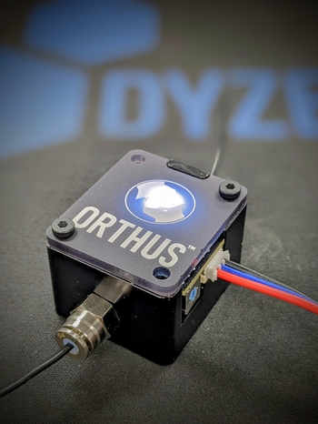
# Labels and indicators
- The LED indicates the Orthus is powered and ready to use.
- The same flashing LED indicates filament movement.
- A lit LED indicates a logical high at the output.
- The numbers below the rotary indicate the possible modes the Orthus can be used in. Each of these modes have different sensibilities. The fourth mode deactivates the output.
See the table below for the possible modes and their sensibilities.
Measured pulses/mm for a hard filament*:
| Rotary switch position | 1 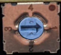 | 2 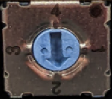 | 3 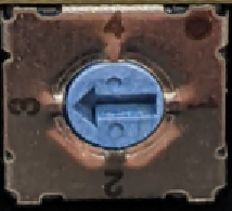 | 4  | |
|---|---|---|---|---|---|
| 1.75mm version | pulses/mm | 102.7 | 6.421 | 0.803 | N/A |
| mm/pulse | 0.010 | 0.156 | 1.246 | N/A | |
| 2.85mm version | pulses/mm | 101.9 | 6.371 | 0.796 | N/A |
| mm/pulse | 0.010 | 0.157 | 1.256 | N/A |
* Values are for reference only, as they can vary slightly depending on the Othus unit, filament hardness, filament diameter and your setup.
# Mounting
Use the two provided screws to mount the orthus on your printer.
The Orthus can be installed before or after your extruder depending on your printer setup.
TIP
The closer the Orthus is to the extruder, the more accurate the readings will be.
WARNING
Always respect the filament insertion direction indicated on the Orthus. The Orthus should always be orientated so that the filament is inserted in the direction of the arrow situated on the cover.
WARNING
When extruding flexible filament, always position the Orthus directly next to the extruder. Failure to do so will result in very inaccurate readings and very slow detection delays.
# Wiring
| Cable Color | Connection |
|---|---|
| Black | Ground |
| Blue | Signal |
| Red | +5V |
# Pins
The easiest pins to use for the Orthus are the followings:
- Servo pins
- Endstop pins
Servo pins always have the right pins: 5V, Ground and Signal.
Most endstop pins will have the same 3 pins, and sometimes only Signal and Ground.
If you only have these two, there should be a 5V/3V somewhere else on your main board.
It is also possible to use the following pins:
- Expansion pins
- Communication pins
For the use of these pins, some boards are very limited and a deeper understanding is required for connecting the Orthus properly.
For pins location examples, refer to the “Connections examples” of our Sentinel™ support page, since the Sentinel uses the same pins.
# Connection examples
# Duet boards
# Duet Mainboard
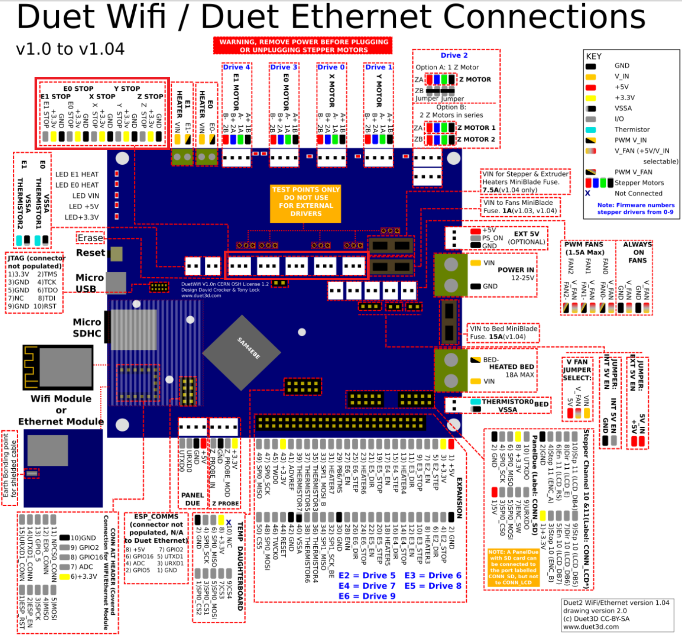
The signal output of the Orthus should be connected to an endstop connection; normally E0 or E1, but can also be connected to the X, Y or Z endstops.
(See the Duet Wifi pinout below for a red highlight of the specified pins).
# Duet Expansion boards
WARNING
The Orthus isn’t compatible with the endstops pins on Duet 2 Expansion boards as they only work with simple filament detection sensors (presence sensor) and not complete motion detectors.
If you have Duet 2 expansions boards, no free endstops pins left on the Duet 2 mainboard, but do not use the CONN_LCD connector, the Signal wire from the Orthus could then be connected to CONN_LCD Stop 11 (ENC_A) or CONN_LCD Stop 10 (ENC_B).
The Ground wire can be plugged to CONN_LCD GND or CONN_SD GND.
The 5V wire can be plugged to CONN_LCD +3.3V or CONN_SD +3.3V.
Pins names to use in the M591 command are as follows:
For RepRapFirmware 3.x and later:
connlcd.encaforCONN_LCD Stop 11 (ENC_A)
connlcd.encbforCONN_LCD Stop 10 (ENC_B)Examples:
M591 D0 P7 C"connlcd.enca" S1 Rxx:yyy Lxxx Exxx
M591 D1 P7 C"connlcd.encb" S1 Rxx:yyy Lxxx Exxx
For RepRapFirmware 2.x:
C11forCONN_LCD Stop 11 (ENC_A)
C10forCONN_LCD Stop 10 (ENC_B)Examples:
M591 D0 P7 C11 S1 Rxx:yyy Lxxx Exxx
M591 D1 P7 C10 S1 Rxx:yyy Lxxx Exxx
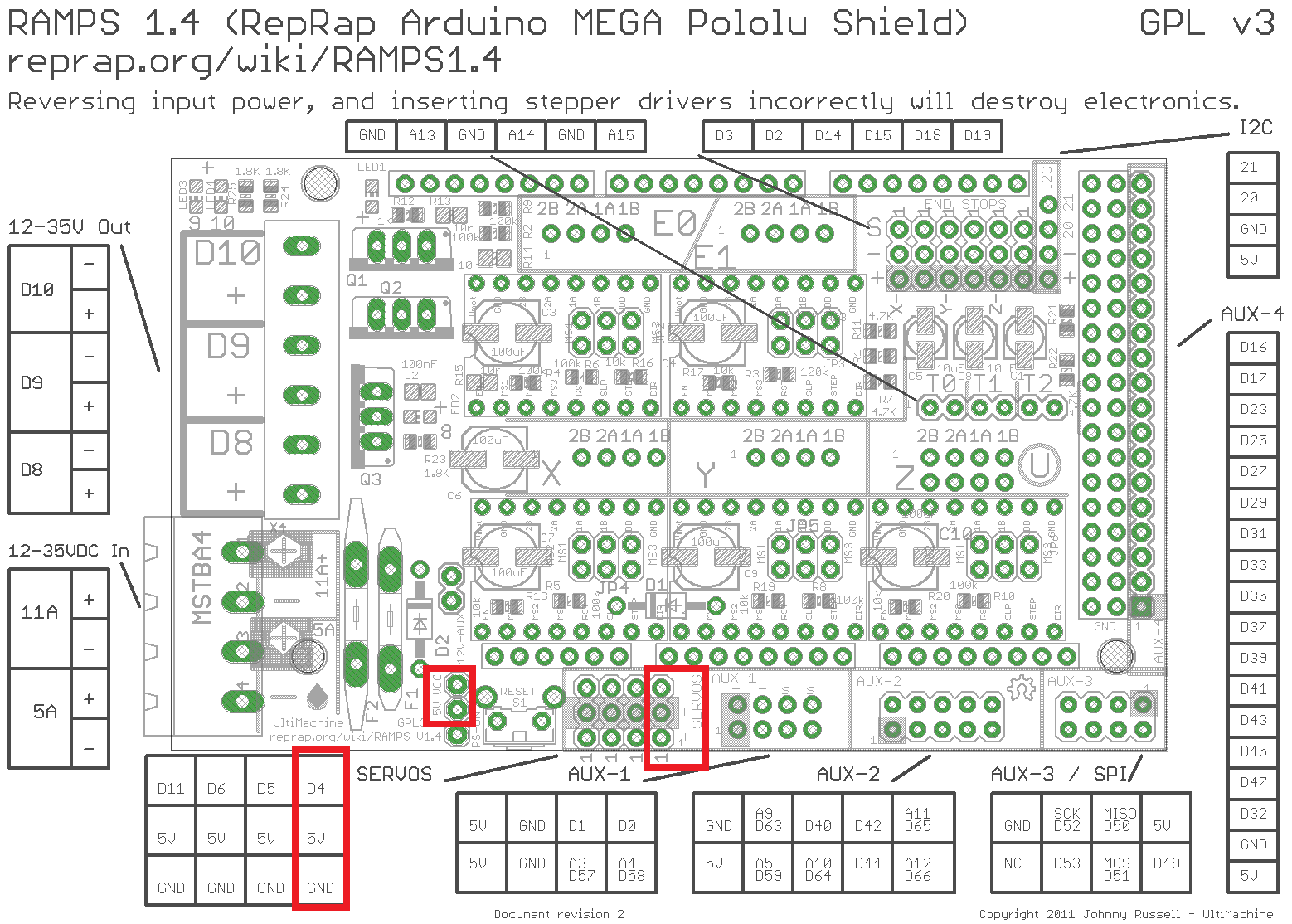
# Ramps 1.4
- Connect the signal output to the D4 SERVOS pins.
- Connect the power and ground connectors to the 5V and ground pins associated with the D4 pins.
- Use a jumper to connect the VCC pin to the 5V pin to power the SERVOS pins.
(See the Ramps 1.4 pinout below for a highlight of the specified pins).
# Firmware Configuration
# Marlin Firmware
The Orthus works with Marlin 2.0 and up. You will need to uncomment the following lines of code:
# Configuration.h
#define FILAMENT_RUNOUT_SENSOR
#define FILAMENT_RUNOUT_DISTANCE X
#define FILAMENT_MOTION_SENSOR
#define NOZZLE_PARK_FEATURE
The "X" in FILAMENT_RUNOUT_DISTANCE needs to be set to the following whole values depending on the position of the rotary switch.
| Rotary rotary switch position | 1 | 2 | 3 | 4 |
|---|---|---|---|---|
FILAMENT_RUNOUT_DISTANCE | 1 | 4 | 7 | N/A |
The FILAMENT_RUNOUT_DISTANCE can be set at a higher whole value than the one given in the preceding table. Increasing this value will lower the sensitivity of the Orthus but will reduce the chance of getting false positives.
# Runout.h
#define FILAMENT_RUNOUT_SENSOR_DEBUG
# Configuration_adv.h
#define ADVANCED_PAUSE_FEATURE
# pins_XXX.h or pins_YYY.h
Depending on your board you will have to search your board manufacturer pinout diagram to find the code of the pins you will connect the Orthus to.
Ex: for the MKS GEN L V2, the Z-max endstop where we will connect the Orthus is D19.
In the Marlin firmware folder, look for Marlin > src > pins and find the appropriate pins_XXX.h file where XXX is your board name.
If the pins_XXX.h file of your board have #include "pins_YYY.h" at the end of the code where YYY is another board, find and modify pins_YYY.h instead
Ex: for the MKS GEN L V2, the appropriate pins file is located in Marlin > src > pins > ramps > pins_MKS_GEN_L_V2.h. However, pins_MKS_GEN_L_V2.h contains #include "pins_RAMPS.h" so we will look for and modify pins_RAMPS.h instead
In the pins_XXX.h or pins_YYY.h file, search those lines:
#ifndef FIL_RUNOUT_PIN
  #define FIL_RUNOUT_PIN Z
#endif
Replace "Z" by the code of the pins you are using for the Orthus
Ex: for the MKS GEN L V2 and the Z-Max endstop
#define FIL_RUNOUT_PIN 19
Once these changes have been made, flash the firmware.
# RepRap Firmware
The Orthus requires RepRap firmware 2.03 or later running on the Duet.
The filament monitor is configured using the M591 command (follow this link (opens new window) for further explanations of the different parameters of the command).
Following is an example of the command:
M591 D0 P7 C3 S1 R70:130 L0.156 E0.625
- Orthus pulse generating sensor (
P7) for extruder drive 0 (D0) is connected to E0 endstop input (C3) - Filament monitoring enabled (
S1) - 70% to 130% tolerance (
R70:130) - Sensitivity 0.156mm/pulse (
L0.156) - 0.625mm detection length (
E0.625)
A lot of these values will need to be tweaked to obtain a well calibrated system.
The starting values for E and L should be set depending on the rotary switch position, the hardness of the filament and the permitted deviation you desire.
# Hard Filaments
| Rotary switch position (Sensitivity) | Permitted deviation “R” (%) | Detection length “E” (mm) | Sensitivity “L” (mm/pulse) |
|---|---|---|---|
| 1 (Most sensitive*) | 50:150 | 1.2 | 0.01 |
| 85:115 | 4.6 | 0.01 | |
| 2 | 50:150 | 0.8 | 0.156 |
| 85:115 | 4 | 0.156 | |
| 3 (Least sensitive) | 50:150 | 5.2 | 1.246 |
| 85:115 | 5.2 | 1.246 |
# Soft Filaments
| Rotary switch position (Sensitivity) | Permitted deviation “R” (%) | Detection length “E” (mm) | Sensitivity “L” (mm/pulse) |
|---|---|---|---|
| 1 (Most sensitive*) | 50:150 | 5.4 | 0.010 |
| 85:115 | 17.8 | 0.010 | |
| 2 | 50:150 | 2.4 | 0.156 |
| 85:115 | 9.4 | 0.156 | |
| 3 (Least sensitive) | 50:150 | 5.2 | 1.246 |
| 85:115 | 8.6 | 1.246 |
* In theory, the rotary switch position “1” is the most sensitive, but it is so sensitive that vibrations from the printer moving during a print cause false positives on the pulses sent, causing error in the readings. It is recommended to use only in setups where the Orthus is completely immobile (per example, on a bowden setup). In which case, the E value can be lowered.
# Quick Setup
WARNING
Choosing to opt for the “quick setup” will result in an increased amount of false positives and a lower sensitivity as the proposed settings are not calibrated to fit your exact system.
If you do not require an extremely accurate reading of the Orthus, you can use any combination of rotary switch position, “R”, “E” and “L” given in the preceding table.
Following is a table of settings examples (for extruder drive 0 and E0 endstop input):
| Filament | Objective | Rotary switch position | Recommended M591 Command |
|---|---|---|---|
| Hard Filament | Quicker filament presence detection, lower sensitivity for jam detection | 2 | M591 D0 P7 C3 S1 R50:150 L0.156 E0.8 |
| Slower filament presence detection, higher sensitivity for jam detection | 2 | M591 D0 P7 C3 S1 R85:115 L0.156 E2.4 | |
| Soft Filament | Quicker filament presence detection, lower sensitivity for jam detection | 2 | M591 D0 P7 C3 S1 R50:150 L0.156 E4 |
| Slower filament presence detection, higher sensitivity for jam detection | 2 | M591 D0 P7 C3 S1 R85:115 L0.156 E9.4 |
Add the adequate M591 Command for your setup in the "Config.g" file of the firmware.
# Accurate Setup
This method requires a calibration of the parameters to fit your extruder. Follow these steps to calibrate the system:
Open your slicer and enter your printer settings. Enter the M591 command with the correct E and L starting parameters (found in the first table of the “RepRap firmware” section) in the “Custom Start G-Code” window. Raa:bb should be set at R0:1000 for the calibration so the calibration print can run its course without being interrupted.
In the “Custom End G-Code” window, enter M591 DX, where “X” is your extruder drive number.
Slice the Orthus_Calibration_Print_1.75mm.stl (opens new window) or the Orthus_Calibration_Print_2.85mm.stl (opens new window) file (depending on your filament size) and print it.
Once the print is finished, the firmware will report the measured mm/rev over the print as well as its variation. The measured mm/rev should be set as your new L parameter value.
The R parameter values should be set to be a fair margin bigger than the reported value of the variation. For example, if the measured variation was 90-110%, it would be safe to input an R value or R75:125 (75-125%).
If the reported variation is larger than you would like, the E parameter value should be doubled.
WARNING
If the E parameter becomes too big and the detection time hence becomes too long, it probably means that your Orthus is situated too far away from the extruder and hysteresis in the filament is causing wrong readings. Install the Orthus closer to the extruder to solve the issue.
Restart steps 1 to 6 with the new E, R and L parameters, until the reported variation is well within the R range. Keep the variation range the closest possible to 100% for more accurate detections of flow reduction. Know however that the system will be more prone to false positives as its sensitivity is increased.
Once correct E, L, and R values have been determined, add the adequate M591 Command for your setup in the "Config.g" file of the firmware and erase the m591 command from the “Custom End G-Code” window so that all your next prints get protected.
WARNING
It is necessary to recalibrate the system once a change has been made in the system. Recalibration-worthy changes include:
- Changing the filament used from a flexible one to a hard one or vice versa.
- Switching the configuration from 1.75mm to 2.85mm filaments or vice versa.
- Moving the Orthus closer or farther away from the extruder.
- Changing the rotary switch position.
# Klipper Firmware
The Orthus works with Klipper 0.10.0 and up.
In printer.cfg file, add a new section [filament_motion_sensor]:
[filament_motion_sensor Orthus]
detection_length: xxx
#   The minimum length of filament pulled through the sensor to trigger a state change on the switch_pin (see table below)
extruder: YourExtruder
#   The name of the extruder section this sensor is associated with (the same name used in your config file).
#   This parameter must be provided.
switch_pin: yyy
pause_on_runout: True
#runout_gcode: YourRunoutGcode
#insert_gcode: YourInsertGcode
#event_delay:
#pause_delay:
The detection length is the minimum length of filament pulled through the sensor to trigger a state change on the switch_pin. It depends on the switch position of the Orthus. This value will need to be tweaked in order to obtain a well calibrated sensing. You can refer to the table below to help you find the best value.
| Rotary switch position | detection_length | |
|---|---|---|
| Hard filament | Soft filament | |
| 1 | 1.4* | 2.7* |
| 2 | 0.8 | 1.8 |
| 3 | 1.0 | 2.0 |
* In theory, the rotary switch position “1” is the most sensitive, but it is so sensitive that vibrations from the printer moving during a print cause false positives on the pulses sent, causing error in the readings. It is recommended to use only in setups where the Orthus is completely immobile (per example, on a bowden setup). In which case, the detection_length value can be lowered.
The detection length can be set at a higher value than the one given in the preceding table. Increasing this value will lower the sensitivity of the Orthus but will reduce the chance of getting false positives.
In klipper, pin definition is the same as the mcu one. So you have to know which microcontroller you’re using to identify the pin connected to the Orthus. See your board's manufacturer documentation to find the appropriate code.
Ex: For the MKS GEN L v2.0 the code for the Y min endstop is PJ1
switch_pin: PJ1
WARNING
With the Mainsail or Fluidd interface, do not refer to the filament presence status “empty” or “detected” to check if the Orthus functions properly. Instead look for a change of status when inserting or removing filament or extruding/retracting, a firmware restart might be needed to see this change.
Ex: Filament is already inserted when powering up the printer, yet in the interface the Orthus status shows “empty”. When we send an extrusion command and the filament starts to move the status changes to “detected” even though filament was already inserted. Look for this behavior when testing as the Orthus isn't a filament presence detector, but a filament movement detector.
# Slicer Configuration
# Marlin Firmware
The FILAMENT_RUNOUT_DISTANCE (descussed earlier in the “Marlin Firmware” configuration sub-section) can also be configured in the slicer. To do so, follow the following steps:
Open your slicer and enter your printer settings.
In the
Custom Start G-Codewindow, enter theM412 S1 Dycommand (whereyis the value of theFILAMENT_RUNOUT_DISTANCEconstant you set in the “Marlin Firmware” configuration sub-section)The filament runout detection will be activated for all of your next prints sliced using this slicer configuration.
# RepRap Firmware
The M591 command (described earlier in the “RepRap Firmware” configuration sub-section) can also be configured in the slicer. To do so, follow the following steps:
Open your slicer and enter your printer settings.
In the
Custom Start G-Codewindow, enter theM591command using the parameters set in the“RepRap Firmware” configuration sub-sectionThe filament runout detection will be activated for all of your next prints sliced using this slicer configuration.
# Troubleshooting
# False positives
In case of a false detection, many options can solve the issue.
The most reliable option remains to mount the Orthus filament monitor closer to the extruder to eliminate filament hysteresis. If the Orthus is already as close as it can be to the extruder, the following actions should be able to eliminate the false positives.
Ensure your filament is within the specifications. A filament too small might not be detected while a filament too large might cause errors in the readings.
Ensure the wiring is well connected and remains well connected during movement of the extruder (no pulling on the wiring depending on the head position). Wiring connection issues can trigger false positives. A badly connected wiring will flash the LED (and the signal) if the connector is wiggled.
# False positives - Marlin firmware
- Increase the value of
FILAMENT_RUNOUT_DISTANCE. Remember that it must remain a whole number. Enter theM412 S1 Dycommand in your slicer where y is the value of theFILAMENT_RUNOUT_DISTANCEconstant.
# False positives - RepRap firmware
Double the
Evalue in theM591command. If doing so brings your detection distance to an unacceptable value, skip to the next solution.Add +- 10 to the
Rrange. For example, if yourRparameter wasR80:120, bring it toR70:130. Repeat this step if needed until no false positives are detected anymore. Do not bring the lower value below 10.
# Maintenance
# Cleaning your Orthus
Some dust and debris might slip through and accumulate in the Orthus over a long period of time. It is recommended to open up the Orthus and clean it inside out every 5 to 15 kg.
WARNING
Do not overtighten any part of the assembly. Failure to do so will damage the bearings and/or PCB and/or acrylic plate. A light tightening suffices.
Disconnect the connector to turn the Orthus off.
Unscrew the 2 M3x0.5x10 low profile screws.
Remove the acrylic plate.
Unscrew the M3x0.5x4 low profile hex screw.
Remove the PCB.
Remove the M3x0.5x11 shoulder screw holding the right wheel in place.
Remove the wheel.
Remove the M3x0.5x4 low profile hex screw maintaining the magnet wheel in place.
Remove the magnet wheel.
With a dry cloth or brush, remove any accumulated dust from the wheels and their housings. If necessary, use a compressed air duster to remove the remaining dust.
Use a compressed air duster to blow away any dust on the PCB. Make sure no condensation forms on the PCB. If so, dry it off carefully with a dry cloth.
Reinstall the magnet wheel.
Fasten the M3x0.5x4 low profile hex screw maintaining the magnet wheel in place.
Reinstall the rubber wheel.
Fasten the M3x0.5x11 shoulder screw holding the rubber wheel in place.
Reinstall the PCB.
Fasten the M3x0.5x4 low profile hex screw holding the PCB.
Reinstall the acrylic plate.
Fasten the 2 M3x0.5x10 low profile screws holding the acrylic plate.
Reconnect the connector to turn the Orthus on again.