# Pulsar™ Atom Precision Pellet Extruder
- Revision
- Specifications
- General
- Safety Notice
- Critical Do's & Don'ts
- Use only pellets up to 5mm in length
- Use with proper product cooling (Air or Water)
- Never drill any parts from the product
- Avoid prolonged idle periods
- Avoid collision with printed part by using vertical lift
- Prevent extended exposure to acidic materials, even during downtime
- Be cautious of excessive retraction
- Watch out for overcurrent on the motor
- Unboxing and Initial Assembly
- Installation / Mounting
- Wiring
- Stepper Driver
- 3D Printer Guideline
- Robotic Arm Guideline
- Firmware
- Using the Pulsar™ Atom extruder
- Maintenance & Troubleshooting
- Risk Assessment
- Pulsar™ Atom Extruder authenticity and informative markings
- Components Technical Datasheet
# Revision
| Date | Revision | Modifications |
|---|---|---|
| 2023-11-28 | R001 | Initial Release |
| 2024-05-28 | R002 | Changes to reflect the production version & CE certification |
| 2024-10-08 | R003 | Added different available screw types & updated instructions on Hotzone installation |
| 2026-05-13 | R004 | Adjusted the suggested layer height as the original values were too high |
| 2026-06-12 | R005 | Added details regarding PWM frequency in heaters |
# Specifications
See product specification here. (opens new window)
# General
# What’s Included
| Item | Quantity |
|---|---|
| Pulsar™ Atom Precision Pellet Extruder | 1 |
| Mounting Hardware (4* M4 x 10 Low Profile Cap Screw | 1 |
# Available accessories with your Pulsar™ Atom Extruder
| Item | Quantity |
|---|---|
| 25A 660VAC Solid State Relay (SSR) | 2 |
| Stepper Driver: - Dyze Design’s Digital Stepper Motor Driver - Ethernet/IP Stepper Driver (STF06) | 1 |
| Cable Harness (5m long) - Hotzone - Coldzone - Power harnesses | 1 |
| PT100 Amplifier Boards - Dyze Design’s PT100 Amplifier Boards - Duet PT100 Daughter Boards | 2 |
| PID Temperature Controller (NOVUS N1040) | 1 |
| Dyze Design’s Liquid Cooling System | 1 |
| Dyze Design’s Pellet Feeding System | 1 |
| Liquid Cooling Fitting Kit - 4* M8 x 1.00 Elbow - 2* M8 x 1.00 Plug - 2 * Water Cooling Blocks - Required Fasteners | 1 |
| High Temperature Liquid Cooling Tubing | Sold by the meter |
| High Temperature Pellet Sensor | 1 |
| Part Cooling Kit - Axial Fan Assembly - 2* Part Cooling Bracket - Required Fasteners | 1 |
* If you need any of these items, contact sales.
# What’s required
- 24VDC Power Supply (1A)
- Required for the Pulsar™ Atom cooling fan (0.15A)
- Required for the pellet sensor
- Required for the Part Cooling Add-On (2 * 0.25A)
- 12VDC Power Supply (2A)
- Required for the Water Cooling Add-On (2A) (if using Dyze Design liquid cooling)
- 24-48VDC Power Supply (1.5A)
- For driving the stepper driver
- AC supply 50 or 60 Hz required for the heating elements totaling 400W
| Heater Nominal Tension (V) | Lower range (V) | Higher range (V) |
|---|---|---|
| 110V Heatcore | 100 | 130 |
| 220V Heatcore | 200 | 240 |
Note : Power is sized based on nominal tension value. Power will be reduced or increased depending on supplied voltage according to Ohm’s Law
- 2 x PT100 Amplifier circuits.
- Dyze Design amplifier
- RTD Amplifier for Duet & RepRapFirmware
- Any other equivalent
- Any open-source, firmware available, 3D Printer Controller Board
- Open Source types:
- Duet3D
- BTT SKR
- BTT Octopus
- MKS
- SmoothieBoard
- Rambo
- CNC Type
- 4th axis
- Temperature control
- Robotic Arm
- Dyze’s RoboSync Hub Controller
- Open Source types:
- Liquid Cooling System (if using Water Cooling Add-on)
- Dyze Design can offer a custom liquid cooling system tailored for 3D printing as an add-on with your extrusion system
# Safety Notice
Heat Hazard
This product generates heat and can cause burns. When performing maintenance, ensure it has cooled down completely before touching any heated parts.
Electrical Hazard
During maintenance, exercise extreme caution to prevent electric shock. Ensure the product is disconnected from the power source before performing any maintenance tasks. Do not touch exposed wires or components. Prioritize safety at all times.
Hazardous Emissions
Some polymers used in this extruder may be hazardous. It is the user's responsibility to check the safety data sheets of the polymers used and to ensure their proper handling. If necessary, a safe enclosure with the appropriate filtering device must be implemented to contain and mitigate any emissions during operation.
# Critical Do's & Don'ts
# Use only pellets up to 5mm in length
This product achieves optimal performance with pellets that are 5mm or shorter, measured as the maximum (longest) straight-line distance from one end to the other. While pellets larger than 5mm might work occasionally, their stability is not guaranteed. Using pellets longer than 5mm can block the extrusion screw, hindering the operational process. Refer to our Pellet’s Requirement section for more details.
# Use with proper product cooling (Air or Water)
Insufficient cooling on the feeding section can lead to overheating and malfunctioning of the product. In such cases, you may need to remove the heatzone for maintenance to clear any clogs.
# Never drill any parts from the product
Some parts are hardened, others have a specific surface roughness. The drill could damage or get broken and stuck inside the unit.
# Avoid prolonged idle periods
Avoid operating the product for prolonged durations without extrusion: In some instances, this may cause polymer degradation, leading to system clogs.
# Avoid collision with printed part by using vertical lift
To avoid collisions with the printed part, consider using a vertical lift strategy. The vertical lift should be at least equal to the layer thickness. For example, for layers of 1.00mm, lift the head by 1.00mm. It's worth noting that slicers aren't yet optimized for large prints, so you may notice many over-extruded sections. Lifting the head will prevent any collision with the printed part and help prevent equipment damage, ensuring smooth and uninterrupted printing processes.
# Prevent extended exposure to acidic materials, even during downtime
To prevent extended exposure to acidic materials, even during downtime, ensure that these materials are not left in the barrel. Regularly purge such materials to avoid degradation of the equipment. Below is a list of polymers and additives to watch out for (this list is not exhaustive):
- PVC (Polyvinyl Chloride)
- Chlorine Release: When heated, PVC can release hydrochloric acid (HCl), which is highly corrosive to steel components.
- Degradation Products: Over time, these can accumulate and exacerbate corrosion.
- Fluoropolymers
- HF Formation: Processing fluoropolymers can lead to the formation of hydrofluoric acid (HF), a very aggressive acid that corrodes most metals.
- Acidic or Basic Polymers
- Polyamide (Nylon): Can absorb moisture and lead to acidic conditions within the extruder.
- Polylactic Acid (PLA): When degraded, it can produce lactic acid, which is corrosive.
- Polyurethanes: Certain formulations can degrade into acidic or basic byproducts.
- Additives and Fillers
- Flame Retardants: Often halogenated, they can release corrosive gasses when heated.
By following these guidelines, you can help ensure the longevity and proper functioning of your screw extruder.
# Be cautious of excessive retraction
Refer to the retraction section for guidelines. Retracting beyond half a turn can lead to molten polymer traveling upward in the system, causing clogging issues.
# Watch out for overcurrent on the motor
Overcurrent can cause the motor to overheat, increasing the temperature in the feeding section. This may result in malfunction and clogging.
WARNING
Motors damaged by overcurrent are not covered under our warranty policy. Each product's motor is tested to ensure proper function before shipping.
# Unboxing and Initial Assembly
# Intended Use
The Pulsar™ Atom is a precision-engineered 3D printing solution optimized for industrial use. Its versatility extends to compatibility with a broad spectrum of thermoplastics commonly found in industrial settings. Designed to boost production efficiency, this innovation embodies our commitment to advancing industrial manufacturing processes.
WARNING
It is of critical importance that you carry out an inspection upon unboxing your Pulsar™ Atom Extruder. In the unlikely event that there’s damage or any issue, get in touch with Dyze Design’s support team.
Dyze Design is not responsible for the Atom's control, integration to the 3D printer or robotic arm (summarized as motion system) and firmware.
Safe control and operation of the Atom requires the motion system to have a proper firmware with enabled safety features compiled by qualified personnel as well as a physical emergency button which cuts power to the Atom. Safe maintenance requires the Motion System to be powered off and for the Atom and the motion system to have cooled down.
Safe maintenance is to be done by qualified personnel familiar with this user manual.
Contact our support team if you require assistance.
INFO
Training and specialized support could also be offered on demand as part of our service plans. (Contact sales for more information)
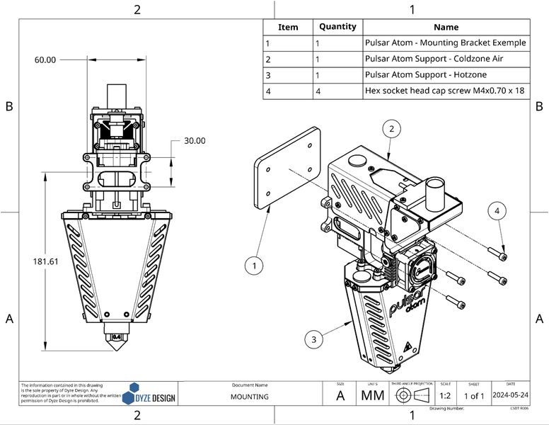
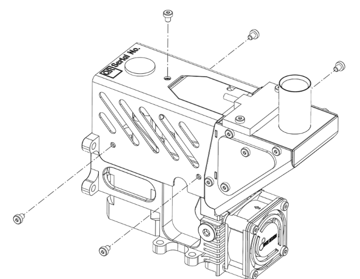
# Installation / Mounting
The Pulsar Atom is mounted from the front using 4 X M4 thru holes.
Check out our drawing page to get the 3D STEP file. Design your bracket according to the available mounting options.
On the CAD file, consider the following references:
- 4.20mm holes are clearance for M4 screws
# Water Cooling Add-On
The Pulsar™ Atom comes with an air cooling system, engineered to operate effectively at ambient temperatures not exceeding 60°C. To enhance operating temperature, we offer the choice of incorporating a water cooling system allowing for sustained functionality at temperatures of up to 150°C. The two water loops are:
- Motor Cooling Block (preinstalled on LC version)
- Main Casing (fittings installed on LC version)
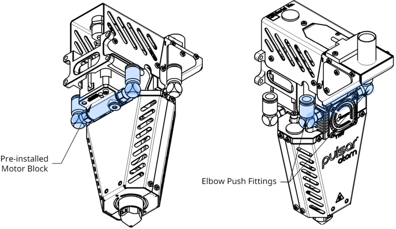
Recommended Tubing : Ø6.35 mm (1/4") ID x Ø9.53mm (3/8") OD rated for push to connect (Durometer≈90A)
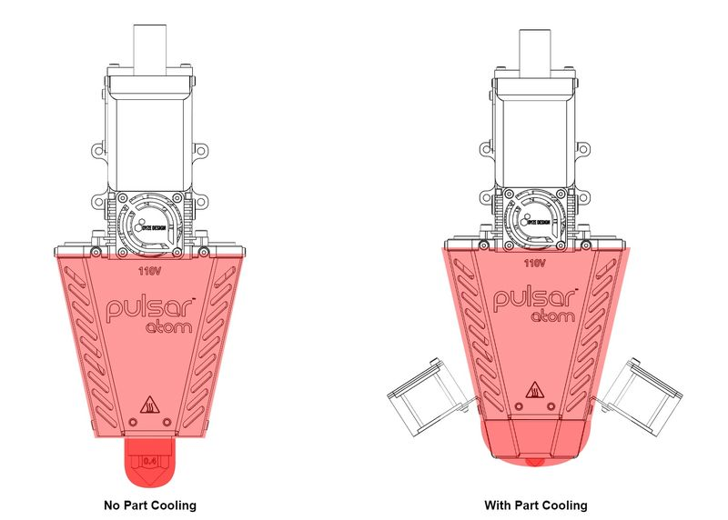
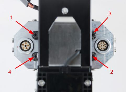
# Part Cooling Add-On
If your polymers require active cooling, you can choose to install an additional part cooling accessory. The fans in this add-on come pre-equipped with PWM capabilities.
| PWM Operation | |
|---|---|
| Voltage | 0V - 5V |
| Frequency | 25 Khz |
To install it, follow these steps:
- Loosen the M3 screws located at the bottom of the Hotzone shield [1] on both sides.
- Gently press the bracket [2] against the nozzle [3] to ensure there is no gap between the nozzle and the bracket.
- Secure the bracket in place using the provided M3X0.5 X 8 screws [4].
- Connect the fans [5] to the connector located beneath the motor at the rear of the Hotzone.
These steps ensure the proper installation of the part cooling add-on, enhancing the cooling capabilities of your system for optimal performance with specific polymers.
# Bed Leveling Accessories
While we do not offer a specific bed leveling solution, our product features four M3 mounting holes on the hotzone shield. These holes allow you to easily mount a bed leveling accessory of your choice. Additionally, the part cooling connector includes dedicated pins for this type of application.
# Wiring
It is possible to order pre-made harnesses that are 5m in length designed to connect the Atom to your printer. The diagram below provides additional details regarding the electrical connections:
# Emergency Stop
The Pulsar Atom Extruder does not have an emergency stop feature. An emergency stop loop is a must to operate the Extruder safely. The emergency stop must cut the power to the heating elements and the power supply of the motor. This feature can be implemented in your 3d printer firmware and control interface or physically in your control cabinet.
# Temperature Sensors (PT100)
The Pulsar™ Atom employs two PT100 sensors for temperature monitoring, with one sensor allocated for each heated section (Top and Bottom). To integrate these sensors with your printer/robot controller board, you will require PT100 amplifier boards. Any amplifier circuit will suffice, PT100 are widely standardized. We also offer our proprietary Dyze PT100 amplifier board, conveniently accessible on our online store (opens new window).
The temperature input control for your 3D printer can be connected to various pins on your controller. These include:
- The standard extruder input pins (E0, E1, E2, etc.)
- Any available expansion pins, which can be identified by referring to the specification pins of your 3D Printer Controller.
For more integration instructions, please refer to our amplifier board documentation page (opens new window).
Note
When using the Dyze RoboSync Hub Interface to control the extruder with a robotic arm, PT100 amplifiers are not required. The Hub is already equipped to manage the extruder’s PT100 sensors. Contact our sales team to have more information on the RoboSync Hub.
# Heaters
Each heater has its own SSR. Two SSR can be provided with the Atom.
WARNING
Note on SSR Selection and Configuration The SSRs provided are zero-crossing types, which are ideal for reducing electrical noise but require specific timing configurations. Depending on your chosen firmware (such as Klipper, Marlin, or RepRapFirmware), you must configure the PWM frequency for these heater outputs to a low rate, typically around 2 to 3 Hz. Setting the frequency too high will prevent a zero-crossing SSR from switching correctly, leading to unstable temperature control or a complete failure to heat.
An overcurrent protection system must be included to ensure proper safety. Both fuses and circuit breakers are suitable for this purpose. We recommend the following current limits based on the power rating:
- Top heater, 250 Watts, 2.5A for 120VAC and 1.25A for 240VAC systems
- Bottom heater, 150 Watts, 1.5A for 120VAC and 0.75A for 240VAC systems
Many pins can be used as the temperature output control. Your 3D Printer Controller (or motion controller) pins can be as below:
The standard extruder output (E0, E1, E2, etc). These are usually rated at the same voltage as your main power supply (12VDC or 24VDC). Any available expansion pins. These can be determined by checking the 3D Printer Controller specification pins.
Please refer to the above diagram for wiring the Atom.
Note
If using the Dyze RoboSync Hub Interface to control the extruder with a robotic arm, the Hub is already equipped and prewired to manage the extruder’s heaters. Contact our sales team to have more information on the RoboSync Hub.
# Heaters Insulation
Heaters with coil heating elements can sometimes absorb moisture, particularly if they haven't been used for a while. This can lower the insulation resistance, potentially causing a small electrical current to leak to the ground. While this is often harmless, in some cases it can trip a GFCI (Ground Fault Circuit Interrupter) breaker.
To prevent this, especially when starting the heater for the first time or after a long period of disuse, you should perform a dehumidifying maintenance routine. This process, detailed below, will dry out the unit and restore proper insulation levels.
WARNING
You must run this procedure on the first startup. Skipping this step may damage the heater.
Dehumidifying Maintenance Routine
# Stepper Driver
# Using your own stepper driver
It’s possible to use your own stepper driver. However, make sure it can drive the motor with the specifications below, especially the current. We won’t be able to offer adequate support if an insufficient stepper driver is used.
WARNING
Some stepper drivers and electronic boards use peak current for their current rating. Ensure you convert to the appropriate value.
| Drive Voltage | 24-48VDC |
|---|---|
| Motor Current (RMS) | 1.68A |
| Frame size | NEMA17 |
Note
If using the Dyze RoboSync Hub Interface to control the extruder with a robotic arm, the Hub is already including a stepper motor driver to manage the extruder’s screw. Contact our sales team to have more information on the RoboSync Hub.
# Using Dyze Design's Stepper Driver
If you're using our Dyze Stepper Driver, you can refer to our Pulsar Atom Quick Start Guide here..
# 3D Printer Guideline
# General
Printing without cooling is only possible with large parts. Thick and large layers take time to cool down, thus requiring you to reduce speed for small parts.
# Use Z lift
Raising the Z axis between each fast-travel is required. It will prevent any collision with the printed part. See the Slicer section for more info.
# Initial Flow Settings
To start with your extruder, we advise setting your parameters as follows:
- Filament size: 2.85mm
- Steps/mm: 1000 steps/mm
- Microstepping: 3200 microsteps
Using these parameters will provide a good base for calibrating your flow, depending on your specific setup and polymer. Flow calibration is achieved by adjusting the flow pourcentage parameter.
The table below lists certain tested polymers with their testing conditions. Use the pourcentage flow closest to your situation. These values are a starting point; you will need to calibrate the extruder to suit your specific setup.
Follow the guidelines in the "Flow RPM Factor" (opens new window) blog post.
| Polymer | Detailed | Top Heater (℃) | Bottom Heater (℃) | Screw | Nozzle (mm) | Flow-to-RPM Ratio | % Flow | Max flow (mm^3/s) |
|---|---|---|---|---|---|---|---|---|
| PLA | LX175 | 180 | 210 | MC | 2.5 | 2.31 | 79% | 234 |
| PLA | LX175 | 170 | 200 | MC | 1.8 | 1.62 | 55% | - |
| PLA | Ingeo 3D850 | 180 | 210 | MC | 2.5 | 0.97 | 33% | 155 |
| PLA | Ingeo 3D700 | 180 | 210 | MC | 1.8 | 1.7 | 58% | - |
| PETG-GF | Polymaker PETG-1013-GF | 190 | 240 | MC | 2.5 | 1.74 | 59% | - |
| CP-CF | Airtech C250-CF | 300 | 300 | NC | 2.5 | 1.57 | 53% | - |
You may also refer to this table to determine the maximum flow rate that the extruder can achieve. These values represent the maximum capacity; we recommend using 80% of this value to ensure smooth extrusion without any problems.
WARNING
It's important to note that these values are for reference only, as specific materials, nozzle sizes, and temperatures can all affect the maximum flow rate. We encourage users to experiment with their machine to find the optimal settings for their specific setup.
The Flow-to-RPM Ratio is intended for use with robotic arms or systems that control the machine's flow using its RPM. To use this value, refer to our "Flow RPM Factor" (opens new window) blog post.
For example, if you want to extrude 100 mm³/s with PLA LX175 using a 2.5 mm nozzle, the Flow-to-RPM Ratio is 2.
Therefore:
# Width line and layer height
Layer height and width depend on your nozzle size. The table below shows recommended starting points. These values are a safe guide, though experienced users may adjust them. Changing these settings can affect print quality and behavior. Changing the ratio of height to width of the extrusion can change the pressure behavior, surface finish and printing behavior. You can experiment outside these ranges if needed.
For additional details, please consult our informative article. (opens new window)
| Nozzle Size (mm) | Min. Max. Line Width (mm) | Recommended Line Width (mm) | Min. Max. Layer Height (mm) | Recommended Layer Height (mm) |
|---|---|---|---|---|
| 0.40 | 0.50-0.80 | 0.60 | 0.10-0.60 | 0.20 |
| 0.60 | 0.75-1.20 | 0.90 | 0.15-0.90 | 0.30 |
| 0.90 | 1.12-1.80 | 1.35 | 0.23-1.35 | 0.45 |
| 1.20 | 1.50-2.40 | 1.80 | 0.30-1.80 | 0.60 |
| 1.80 | 2.25-3.90 | 2.70 | 0.45-2.70 | 0.90 |
| 2.50 | 3.12-5.20 | 3.75 | 0.63-3.75 | 1.25 |
# Consider thermal expansion
When performing bed leveling at room temperature, it's essential to consider the thermal expansion of the heat cylinder. For example, at an operating temperature of 200°C, the printing head may be 0.25mm lower due to thermal expansion.
Exercise caution during Z homing to account for this effect. For bed leveling with a cold extruder (20°C), make sure you compensate the thermal expansion:
| Temperature (°C) | Extra length (mm) |
|---|---|
| 200 | 0.40 |
| 300 | 0.62 |
| 400 | 0.84 |
# Robotic Arm Guideline
If you plan on installing the Atom on a robotic Arm, you'll need to get some extra hardware to get the same features as a 3D printer controller. These items are the following:
- A motion planner capable of outputting STEP / DIR pulses for the stepper driver.
- Two (2) PT100 temperature sensor inputs.
- Two (2) digital outputs to drive the SSRs.
INFO
Dyze Design is now offering an ethernet/ip controller to enable sync between your robot/robot controller and the Atom extruder (motor & flow control, heating elements, etc). Contact sales for more information.
# Firmware
# Marlin Firmware
2.0.x# Configuration.h
Set number of extruders:
#define EXTRUDERS 2
Set the correct temperature sensor values. Please refer to Marlin thermal settings (opens new window) to find the correct value based on your amplifier circuit or your actual setup.
#define TEMP_SENSOR_0 68 //could also be 20 or 21. Check the Marlin thermal settings.
#define TEMP_SENSOR_1 68 //could also be 20 or 21. Check the Marlin thermal settings.
Set temperature min temp:
#define HEATER_0_MINTEMP 10
#define HEATER_1_MINTEMP 10
Set temperature max temp:
#define HEATER_0_MAXTEMP 500
#define HEATER_1_MAXTEMP 500
The heaters are very powerful, which is required for engineering and advanced polymers. If you are planning on printing low temperature, reduce the bang_max from 255 to 127.
Set temperature bang_max:
#define BANG_MAX 127
Increase the PID_functional_range:
#define PID_FUNCTIONAL_RANGE 40
Set the base PID values:
 #define DEFAULT_Kp 2.85
 #define DEFAULT_Ki 0.07
 #define DEFAULT_Kd 27.57
Set the extruder steps per mm:
TIP
{X Axis, Y Axis, Z Axis, E Axis} The value of the XYZ axis may vary and are shown as XXX.XX. The value of 1000 serves as an initial reference point. Calibration will be necessary to optimize it for your specific configuration. You can find instructions for this calibration process in the "Calibrating the flow" section.
#define DEFAULT_AXIS_STEPS_PER_UNIT { XXX.XX, XXX.XX, XXX.XX, 1000 }
Set the max feed rate:
TIP
{X Axis, Y Axis, Z Axis, E Axis} The value of the XYZ axis may vary and are shown as XXX.XX
#define DEFAULT_MAX_FEEDRATE { XXX, XXX, XXX, 200 }
Switch enable logic for the extruder motor:
#define E_ENABLE_ON 1
# Configuration_adv.h
Configure the external stepper driver
#define MINIMUM_STEPPER_POST_DIR_DELAY 500
#define MINIMUM_STEPPER_PRE_DIR_DELAY 500
#define MINIMUM_STEPPER_PULSE 2
#define MAXIMUM_STEPPER_RATE 200000
# PID tuning
Each heater needs to be tuned separately, use the M303 command in the console to run the tuning cycle as detailed here: https://marlinfw.org/docs/gcode/M303.html (opens new window)
Run the PID tuning without any material inside the barrel or only set a PID target temperature within your material range to avoid clogs.
Example:
M303 E0 S300 ;tune heater 0 with a target temperature of 300C
Once the tuning cycle is completed, save the new heater 0 values by entering the M500 command in the console (only works if EEPROM_SETTINGS is enabled in your firmware).
Repeat the process for the second heater. Example:
M303 E1 S300 ;tune heater 1 with a target temperature of 300C
# RepRap Firmware
TIP
In your configuration file, you should find values similar to the ones below. However, we do recommend that you use the online ReRap Firmware configurator tool (opens new window).
WARNING
The following information is based on Duet 2 and RepRap Firmware 3.x. We strongly suggest that you also read the official Duet/RepRap documentation (opens new window) to make sure you correctly connected and configured your Duet board, PT100 (RTD) amplifier board and RepRap firmware version.
# Config.g
Set the correct temperature sensor values. Please refer to Duet documentation to find the correct value based on your amplifier circuit.
TIP
For the Duet 3 MB6HC, pins spi.cs1 and spi.cs2 should be replaced with spi.cs0 and spi.cs1.
M308 S1 P"spi.cs1" Y"rtd-max31865"    		 	; configure sensor 1 as PT100 on pin e0temp
M308 S2 P"spi.cs2" Y"rtd-max31865"             ; configure sensor 2 as PT100 on pin e1temp
Set temperature max temp:
M143 H0 S500
M143 H1 S500
Set the extruder steps per mm:
M92 XXXX.X YXXX.X ZXXX.X E1000
TIP
The value of 1000 serves as an initial reference point. Calibration will be necessary to optimize it for your specific configuration. You can find instructions for this calibration process in the "Calibrating the flow" section.
Set the max feed rate:
M203 XXXXX YXXXX ZXXXX E3000
Assign heaters 1 and 2 to the same tool:
M563 P0 D0 H1:2 S"PulsarAtom"
Configure external stepper drivers (only if using the external stepper driver):
M569 PXXX SXXX R1 T2
# PID tuning
The two heaters need to be tuned separately as it is not yet possible in RepRap to tune both at the same time.
Run the PID tuning without any material inside the barrel or only set a PID target temperature within your material range to avoid clogs.
Using the M303 command in the Duet console, run the PID tuning for each heater as explained here: https://docs.duet3d.com/User_manual/Reference/Gcodes#m303-run-heater-tuning (opens new window).
Example:
M303 H1 S300 ;tune heater 1 with a target temperature of 300C
Once the tuning cycle is done for heater 1, copy the generated M307 command and replace them in your config.g file to the appropriate line.
Then, we tune heater 2 following the same procedure.
Example:
M303 H2 S300 ;tune heater 2 with a target temperature of 300C
Copy the generated M307 command for heater 2 and replace it in the config.g file.
The heaters are very powerful, which is required for engineering and advanced polymers. If you are planning on printing low temperature, reduce the maximum PWM by 50%.
If you encounter an overshooting error when trying to heat up the two heaters at the same time, try lowering the PWN value of the problematic heater even more.
Set maximum PWM (Change HX by H0, H1, H2, etc. based on your heater configuration):
M307 H1 S0.50	;the S parameter will depend on your setup
M307 H2 S0.40	;the S parameter will depend on your setup
# Repetier Firmware
TIP
In your configuration file, you should find values similar to the ones below. However, we do recommend that you use the online Repetier Firmware configurator tool (opens new window).
# Configuration.h
Set the correct temperature sensor values. Please refer to Repetier configurator tool (opens new window) to find the correct value based on your PT100 amplifier circuit.
#define EXT0_TEMPSENSOR_TYPE 13
#define EXT1_TEMPSENSOR_TYPE 13
Set temperature min temp:
#define MIN_DEFECT_TEMPERATURE 20
Set temperature max temp:
#define MAXTEMP 500
#define MAX_DEFECT_TEMPERATURE 505
The heaters are very powerful, which is required for engineering and advanced polymers. If you are planning on printing low temperature, reduce the bang_max from 255 to 127.
Set maximum power output:
#define EXT0_PID_MAX 127
#define EXT1_PID_MAX 127
Set the extruder steps per mm:
#define EXT0_STEPS_PER_MM 1000
TIP
The value of 818.1 serves as an initial reference point. Calibration will be necessary to optimize it for your specific configuration. You can find instructions for this calibration process in the "Calibrating the flow" section.
Set the max feed rate:
#define EXT0_MAX_FEEDRATE 200
Switch enable logic for the extruder motor:
#define EXT0_ENABLE_ON 1
# Configuration_adv.h
Configure the external stepper driver (if using the external stepper driver):
#define STEPPER_HIGH_DELAY 2
#define DIRECTION_DELAY 2
# PID tuning
Each heater needs to be tuned separately, use the M303 command in the console to run the tuning cycle as detailed here: https://github.com/repetier/Repetier-Firmware/blob/master/src/ArduinoAVR/Repetier/Repetier.ino#L191C3-L194C40 (opens new window)
Run the PID tuning without any material inside the barrel or only set a PID target temperature within your material range to avoid clogs.
Example for heater 0:
M303 P0 S300 X0 R4 C0 ;tune heater 0 with target temperature of 300C, saves result in EEPROM, 4 cycles, classic method
Once the first heater is tuned, run the tuning for the second heater with M303 again.
Example for heater 1:
M303 P1 S300 X0 R4 C0 ;tune heater 1 with target temperature of 300C, saves result in EEPROM, 4 cycles, classic method
# Klipper Firmware
Open the printer.cfg file.
# Create two heaters
The bottom heater will be the one configured in the [extruder] section
Modify the [extruder] section as follows :
TIP
Replace the data in """___""" by your own
[extruder]
step_pin: """ the pin name where the stepper driver pullup + is plugged """
dir_pin: """ the pin name where the stepper driver direction + is plugged """
enable_pin: """ the pin name where the stepper driver enable + is plugged """
# Check you board manufacturer documentation for these informations
microsteps: """ the microsteps settings your stepper driver is set at, ex: 16 """
rotation_distance: 24.92
# This is a starting average value that you will need to calibrate per material
full_steps_per_rotation: 200
gear_ratio: 6.23:1
#step_pulse_duration: 0.000002
# Uncomment the above line if you use the Dyze Stepper Driver
nozzle_diameter: """ your nozzle diameter in mm, ex: 1.2 """
filament_diameter: 2.85
# With the Atom we do not use filament but we calculated other settings with this value
# If you use a bigger nozzle diameter than this value, you will have to also raise the filament diameter parameter to at least the nozzle diameter.
# This is a required Klipper parameter that only affects the max allowed extrusion so it won’t affect your rotation distance value.
heater_pin: """ the pin name where the bottom heater is plugged """
# Check you board manufacturer documentation for this information
sensor_type:  """ your amplifier board name, ex: PT100 INA826, custom pt100_5v or pt100_3v for Dyze PT100 Amplifier Board """
# See https://docs.dyzedesign.com/pt100-amplifier-board.html#klipper if you use our PT100 Amplifier
# See https://www.klipper3d.org/Config_Reference.html#common-temperature-amplifiers for list of compatibles temperature amplifier names
sensor_pin: """ the pin name where the PT100 for the bottom heater is plugged """
# Check you board manufacturer documentation for this information
control: pid
pid_Kp: 2.85
pid_Ki: 0.07
pid_Kd: 27.57
# Starting values to be customized at first use with a PID autotuning routine
min_temp: 0
max_temp: 500
max_power: 1.0
# Try lowering this value if you have temperature overshooting issues
min_extrude_temp: 150
# Can be customized depending on your own material
pressure_advance: 0.0
#To test per material, initially best to keep disabled
The top heater is configured by creating an additional custom heater
In printer.cgf, add the following :
TIP
Replace the data in """___""" by your own
[heater_generic top_heater]
gcode_id: 1
# The id to use when reporting the temperature in the M105 command.
# This parameter must be provided.
# This number will not work with the M104 T1 command, only with the M105 report command
heater_pin: """ the pin name where the top heater is plugged """
# Check you board manufacturer documentation for this information
sensor_type:  """ your amplifier board name, ex: PT100 INA826, custom pt100_5v or pt100_3v for Dyze PT100 Amplifier Board """
# See https://docs.dyzedesign.com/pt100-amplifier-board.html#klipper if you use our PT100 Amplifier
#   See https://www.klipper3d.org/Config_Reference.html#common-temperature-amplifiers for list of compatibles temperature amplifier names
sensor_pin: """ the pin name where the PT100 for the top heater is plugged """
#   Check you board manufacturer documentation for this information
control: pid
pid_Kp: 2.85
pid_Ki: 0.07
pid_Kd: 27.57
# Starting values to be customized at first use with a PID autotuning routine
max_power: 1.0
#   Try lowering this value if you have temperature overshooting issues
min_temp: 0
max_temp: 500
# Calibrate the PID by running a PID autotune routine
Once you have set the heaters in config.g, before using any material you need to run the PID autotuning procedure for each heater separately.
In the command console type and press enter:
PID_CALIBRATE HEATER=extruder TARGET=240
This will calibrate the bottom extruder, we let the top extruder at 0 in the meantime. You can set another target temperature of your choice.
Once the test is completed and the tuning is done, type SAVE_CONFIG in the console to update the config file automatically with the new PID settings.
Once everything has cooled down to ambient temperature, we repeat the process for the top heater by entering in the command console:
PID_CALIBRATE HEATER=top_heater TARGET=240
And then when completed, we save the new settings with SAVE_CONFIG.
Now the two heaters PID are tuned and we can try printing.
TIP
If you encounter an error during PID autotuning with an “extruder not heating at expected rate” warning, verify that the top and bottom heater are each associated with the right pins for the heaters and sensors. If you try to heat the bottom heater and the top heater temperature rises faster, associated heaters or temperature sensors pins may have been switched.
# Control the heaters temperature
In printer.cfg, create or modify your START_PRINT macro by adding the following:
[gcode_macro START_PRINT]
gcode:
  # Set bed, extruder Bottom and Top heaters to reach temperature
  {% set BED_TEMP = params.BED_TEMP|default(60)|float %}
  {% set EXTRUDER_BOT_TEMP = params.EXTRUDER_BOT_TEMP|default(190)|float %}
  {% set EXTRUDER_TOP_TEMP = params.EXTRUDER_TOP_TEMP|default(190)|float %}
  SET_HEATER_TEMPERATURE HEATER=heater_bed TARGET={BED_TEMP} #Bed Heater
  SET_HEATER_TEMPERATURE HEATER=extruder TARGET={EXTRUDER_BOT_TEMP} #Bottom Heater
  SET_HEATER_TEMPERATURE HEATER=top_heater TARGET={EXTRUDER_TOP_TEMP} #Top Heater
  # Use absolute coordinates
  G90
  # Home the printer
  G28
  # Wait for bed to reach temperature
  M190 S{BED_TEMP}
  # Wait for Extruder Bottom and Top heaters to reach the target printing temperature
  {% if EXTRUDER_BOT_TEMP != 0 %}
  TEMPERATURE_WAIT SENSOR=extruder MINIMUM={EXTRUDER_BOT_TEMP} MAXIMUM={EXTRUDER_BOT_TEMP+2}
  {% endif %}
  {% if EXTRUDER_TOP_TEMP != 0 %}
  TEMPERATURE_WAIT SENSOR="heater_generic top_heater" MINIMUM={EXTRUDER_TOP_TEMP} MAXIMUM={EXTRUDER_TOP_TEMP+2}
  {% endif %}
Do the same for the END_PRINT macro:
[gcode_macro END_PRINT]
gcode:
  # Turn off bed, both extruder heaters, and fan
  M140 S0
  SET_HEATER_TEMPERATURE HEATER=extruder TARGET=0 #Cooldown Bottom Heater
  SET_HEATER_TEMPERATURE HEATER=top_heater TARGET=0 #Cooldown Top Heater
  M106 S0
  # Move nozzle away from print
  G91
  G1 Z10 F3000
  G90
  G1 X0 Y0
  # Disable steppers
  M84
  #This is a base to customize to your end print procedure of choice
# Slicer Settings
In your slicer of choice, set your start g-code to this following line, keep it as a single continuous line for it to work:
PRINT_START BED_TEMP={bed_temperature} EXTRUDER_TOP_TEMP={top_temperature} EXTRUDER_BOT_TEMP={bottom_temperature}
Set your end g-code to this:
END_PRINT
INFO
Replace {bed_temperature},{top_temperature} and {bottom_temperature} by your desired values.
Example:
START_PRINT BED_TEMP=80 EXTRUDER_TOP_TEMP=190 EXTRUDER_BOT_TEMP=220
Example for Cura:
M140 S{material_bed_temperature_layer_0}
M104 S{material_print_temperature_layer_0}
START_PRINT BED_TEMP={material_bed_temperature_layer_0} EXTRUDER_TOP_TEMP=240 EXTRUDER_BOT_TEMP={material_print_temperature_layer_0}

;The bottom heater will use Cura print settings temperature
;The top heater will have to be customized each time in start g-code
;If we want the same temps for both heaters we can also set EXTRUDER_TOP_TEMP={material_print_temperature_layer_0}

;M190 S{material_bed_temperature_layer_0}
;M109 S{material_print_temperature_layer_0}
;We use M140 and M104 dummy preheat lines that will be overriden just after
;This is to prevent certain versions of Cura from adding their own automatic ones
If you use Cura and possibly with other slicers you might have to open the gcode in a code editor and remove any automatically generated M104 and M109 commands that could interfere with your custom chosen temperatures.
# Using the Pulsar™ Atom extruder
# Pellet’s Requirement
Given the product's scale, this extruder is tailored for pellets with up to 5mm in length. The length requirement is measured as the maximum straight-line distance from one end to the other (it could be a diagonal).
The following are guidelines concerning pellet size and shape to follow for optimal results with our product:
- Pellets under 5mm in size are optimal.
- Pellets measuring between 5.0mm and 5.2mm are at the threshold of compatibility and will cause instability.
- Pellets larger than 5.2mm will lead to extrusion failure, as they are unable to enter the extrusion screw due to their size, disrupting the extrusion process.
- Cylindrical pellets can be more difficult to work with compared to spherical ones. Whenever possible, opt for spherical pellets.
- It is imperative to use only the specified pellets to ensure correct operation.
WARNING
Be aware that pellet blends can vary in size; some pellets in the same blend may be smaller, while others larger. When assessing compatibility with the Atom extruder, always consider the largest pellets in the blend rather than the average size to ensure optimal performance.
If sourcing pellets poses a challenge, reach out to our sales team. Dyze Design can provide support in sourcing the right material supplier. Dyze can also directly distribute pellets material for the following materials:
- PLA / rPLA
- PETG / rPETG / rPET
- TPU / PEBA
- ASA
- PA6-GF
- PCTG
- PC-GF
*Our range of materials is continuously expanding.
# Tested Compatible Pellets Brands
We have rigorously tested a wide range of pellet materials from various brands to determine their compatibility with the Atom extruder. Below is a curated, yet non-exhaustive and constantly evolving, list of pellet brands that are confirmed to work:
| Material | Brand | Format | Compatibility |
|---|---|---|---|
| rPLA | Reflow | Cylindrical | Good |
| PLA | Xtellar | Cylindrical | Good |
| PLA 3D700 | NatureWorks | Spherical | Limited |
| PLA LX175 Micropellets | Ingenia Polymers | Spherical | Good |
| TPU 80A | Essentium | Spherical | Good |
| PETG | Xtellar | Cylindrical | Good |
| rPETG | Mistubishi Chemicals | Spherical | Good |
| PETG-1013-GF | Polymaker (PolyCore) | Cylindrical | Good |
| rPET | BASF | Cylindrical | Limited |
| ASA-3000 | Polymaker (PolyCore) | Cylindrical | Good |
| CP+ GF | Airtech | Cylindrical | Limited |
# Powering on the unit
Once the unit is mounted, the software is configured and electrical connections are finished. The next step is to power the unit.
While the unit is empty perform the following verification :
- Ensure the cooling system is in proper working condition, whether it is air-cooled or water-cooled:
- For air-cooled systems: Verify that the unit’s fan is operating correctly.
- For water-cooled systems: Pinch a section of the tube to check for air bubbles and listen for changes in the pump noise. This confirms that water is flowing through the system.
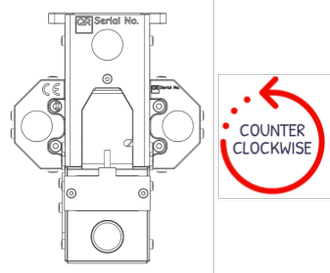
- Low speed extrusion command (5RPM) - Confirm that the screw rotation is counterclockwise when inspecting the screw from the feeding section. Removing the hopper assembly is necessary to inspect the screw.
- Setpoint to a low temperature (50-75°C) on the top heater
- Make sure the matching sensor reads
- Setpoint to a low temperature (50-75°C) on the bottom heater
- Make sure the matching sensor reads
# Pellet Feeding
Pellet feeding into the extruder can be achieved via three distinct methods:
- Automated Pellet Feeding (Dyze Automatic Pellet Feeding System or Custom-Made Solutions)
- Advantages:
- Hopper position and size versatility: These systems allow for flexible placement and sizing of hoppers, adapting to various setups and printing needs.
- "Limitless" 3D printing: With continuous pellet feeding, there's no need to worry about running out of pellets mid-print.
- No added weight on the printhead: Pellets are conveyed when the hopper is low, eliminating the need to carry them and ensuring consistent printing without added weight on the printhead.
- Drawbacks:
- Cost: Automated pellet feeding systems can be more expensive upfront.
- Added complexity: Some systems require a compressor for pneumatic operations, adding complexity and cost to the setup.
- Gravity Feeding
- Advantages:
- Hopper size versatility: The hopper can be of various sizes, accommodating different printing needs.
- Simple: Gravity feeding setups are straightforward and easy to implement.
- Drawbacks:
- Hopper needs to be located on top of the printer/robotic arm: This may limit the design or placement options for the printer.
- Sensitive to blocking depending on tube setup: The feeding tube must be carefully designed to avoid blockages, which can interrupt the printing process.
- On-Board Hopper
- Advantages:
- Simplest: The hopper is directly attached to the printer, simplifying the feeding mechanism.
- Drawbacks:
- Added weight on printhead: The weight of the hopper can affect the printer's performance, especially in terms of speed and accuracy.
- Limited printhead mobility due to the need to maintain a larger hopper level to avoid spilling material: The inclination angle of the product needs to be limited to prevent material from spilling out of the hopper. This limitation can be especially problematic when attempting to print in non-planar situations, as the printhead's range of motion may be constrained by the need to keep the hopper level.
- Limited hopper size based on gantry weight capacity: The size of the hopper is constrained by the weight capacity of the gantry, limiting the amount of material that can be stored.
Each method presents its own set of advantages and drawbacks. This product is chiefly engineered to excel with an automatic pellet feeding system, enriched by its integrated pellet sensor. Nonetheless, when employing gravity feeding, the sensor transitions into a pellet runout detector, broadening its utility.
# Slicer and Print Settings
Set vertical lift to at least your layer thickness. For layers of 1.00mm, lift 1.00mm. Slicers aren’t yet optimized for large prints. Many over-extruded sections will be noticeable. Lifting the head will prevent any collision with the printed part.
Wipe nozzle to at least the line width. For a line width of 3.50mm, wipe 3.50mm or greater.
Set the heating to both heaters to the required temperature in the start Gcode script. Make sure to refer to your slicer documentation for variable names.
M109 T0 S[first_layer_temperature]
M109 T1 S[first_layer_temperature]
- Set end script to turn off both extruders:
M104 T0 S0 ; turn off extruder
M104 T1 S0 ; turn off extruder
- Output flow and pressure greatly changed depending on the printing speed. To get the best result, keep the output flow steady by keeping the same speed everywhere.
# Flow to RPM
For some applications, such as robotic arms, it's easier to configure the motor RPM rather than using the length of material to extrude, as seen in traditional 3D printer controllers. The following table lists the parameters for the F-RPM factor, which is the Flow to RPM variable discussed in our blog post here. (opens new window)
# Pulsar Atom - Early Access
| Polymer | Detailed | Top Heater | Bottom Heater | Screw | Nozzle | Flow-to-RPM Ratio | Max flow (mm^3/s) |
|---|---|---|---|---|---|---|---|
| PLA | LX175 | 180 | 210 | STD | 2.5 | 2 | 278 |
| PLA | LX175 | 180 | 210 | STD | 0.4 | 5.24 | 111 |
| PLA | LX175 | 180 | 210 | NC | 2.5 | 3.71 | 223 |
| PLA | LX175 | 200 | 250 | NC | 2.5 | 3.98 | - |
| PLA | LX175 | 180 | 210 | MC | 2.5 | 3.38 | 294 |
| PLA | LX175 | 200 | 250 | MC | 2.5 | 2.75 | - |
| PLA | Chopped polyterra 1.75-2 | 190 | 210 | STD | 2.5 | 2.81 | - |
| PLA | 3D850 | 200 | 230 | NC | 2.5 | 2 | 310 |
| PLA | 3D850 | 260 | 300 | NC | 2.5 | 1.9 | 376 |
| PLA | 3D850 | 190 | 230 | MC | 2.5 | 1.78 | - |
| PLA | Nucleated_Crystaline | 200 | 200 | STD | 2.5 | 1.97 | 306 |
| PETG | HT | 230 | 240 | STD | 2.5 | 2.95 | 184 |
| PETG | HT | 230 | 240 | MC | 1.8 | 2.52 | - |
| PETG | Xtellar | 170 | 230 | CS | 1.8 | 1.76 | - |
| TPU | 70A | 190 | 205 | STD | 2.5 | 2 | 338 |
| TPU | 80A | 200 | 200 | CS | 1.8 | 2 | - |
| PLA | PLA PRO – Black | 170 | 230 | CS | 1.8 | 1.76 | - |
| PLA | Essential PLA – White | 180 | 200 | CS | 1.8 | 1.76 | - |
| PCTG | Essentium | 200 | 240 | LP | 1.8 | 1.76 | - |
| PEBA | Xenia Polymers | 200 | 240 | CS | 1.8 | 2.35 | - |
| PP | ECC | 210 | 210 | CS | 1.8 | 2.35 | - |
| PC-CF | Xenia Polymers | 240 | 280 | CS | 1.8 | 2.35 | - |
| PETG-1013-GF | Polymaker | 170 | 230 | CS | 1.8 | 2.35 | - |
# Pulsar Atom - Production
| Polymer | Detailed | Top Heater | Bottom Heater | Screw | Nozzle | Flow-to-RPM Ratio | Max flow (mm^3/s) |
|---|---|---|---|---|---|---|---|
| PLA | LX175 | 180 | 210 | MC | 2.5 | 2.31 | 234 |
| PLA | LX175 | 170 | 200 | MC | 1.8 | 1.62 | - |
| PLA | Ingeo 3D850 | 180 | 210 | MC | 2.5 | 0.97 | 155 |
| PLA | Ingeo 3D700 | 180 | 210 | MC | 1.8 | 1.7 | - |
| PETG-GF | Polymaker PETG-1013-GF | 190 | 240 | MC | 2.5 | 1.74 | - |
| CP-CF | Airtech C250-CF | 300 | 300 | NC | 2.5 | 1.57 | - |
# Calibrating the flow
The extrusion throughput depends on various factors, including temperatures, polymer type, nozzle size, pellet geometry, and more. For achieving the best results, we recommend calibrating the flow pourcentage whenever there is a change in a variable that could impact the flow. To perform this calibration, you can use a basic single wall thickness cube. The flow percentage can be adjusted using the following formula:
As an example, let's say we print a 1.5mm wall thickness cube using a 1.2mm nozzle, and initially, the flow percentage is set at 100%. After measuring, we find that the actual wall thickness is 1.69mm. To calculate the new flow percentage, you would use the formula as follows:
Therefore, the new flow percentage should be set to approximately 88.76 for optimal calibration in this scenario.
Achieving precise calibration often requires multiple iterations. Calibrating 2-3 times in a row can help fine-tune the extrusion process and ensure more accurate and consistent results.
# Using retraction
To mitigate oozing and globbing, since there's no inherent anti-oozing feature, retraction can be utilized. Yet, exercising caution during retraction is imperative. In operation, the screw of the pellet extruder should never rotate clockwise beyond half a turn. Too much clockwise retraction could propel melted material into unwanted regions, posing a risk of flow obstructions.
A half turn equates to 10000 steps (given a 3200 steps/revolution setting). Given a setting of 1000 steps/mm, never retreat beyond 10mm.
If a conversion to millimeters (mm) is necessary, employ the formula below:
# Non Planar/Angled Printing
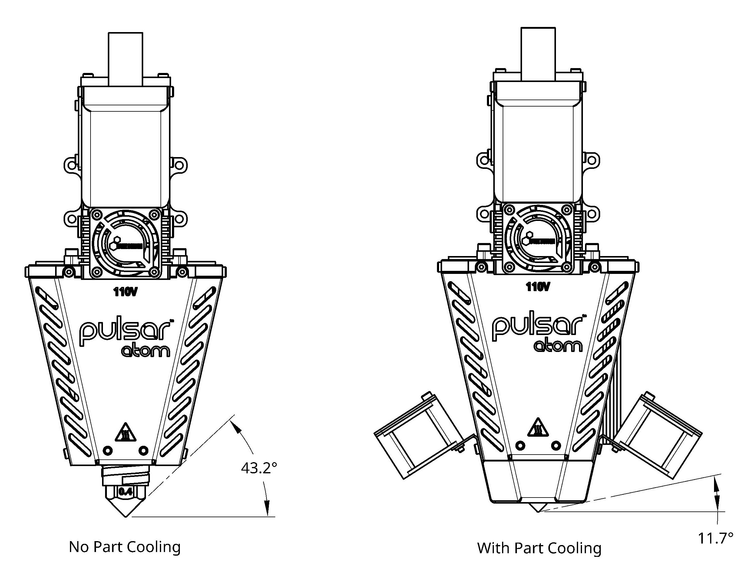
The clearance angle around the nozzle is depicted in the accompanying image. The addition of the Part Cooling Add-On decreases the 43.2° clearance to 11.8°.
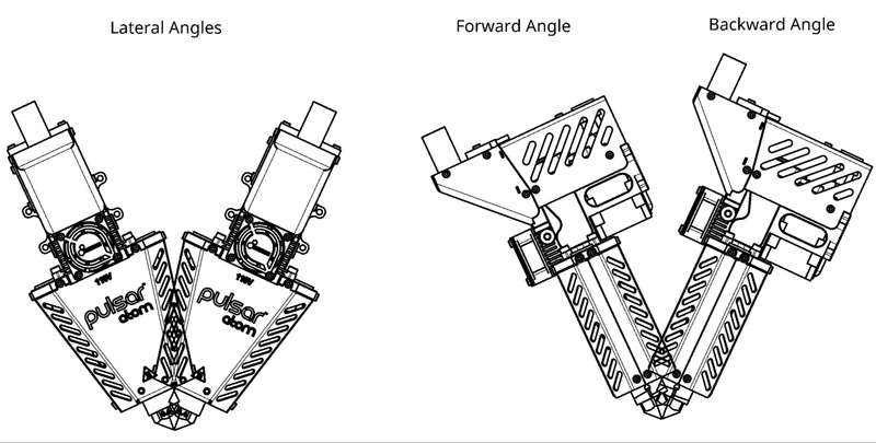
Gravity exerts a significant influence on the flow of pellets, causing a decreased flow rate for the Atom when it is inclined. To ensure optimal performance when inclining the product, please take note of the following recommendations:
- Minimize forward inclinations.
- When possible, favor backward angles over lateral angles.
# High Temperature Use
The Pulsar™ Atom, along with its various add-ons, is designed to operate within an environmental temperature range of up to 60°C. Certain components have temperature limitations as follows:
- The product cooling fan and part cooling fans can both function effectively up to 60°C.
- The pellet sensor has a higher temperature threshold of up to 70°C
If you intend to use this product in an environment with temperatures as high as 150°C, you should take the following factors into account:
- Implement the Water Cooling Add-on.
- Consider our Dyze Design’s Liquid Cooling System, should the need arise.
- Opt for High Temperature Liquid Cooling Tubing.
- Replace the included pellet sensor with a high-temperature version.
- Ensure that the pellet convey tubing is resistant to high temperatures.
- Ensure that the cable harnesses are resistant to high temperatures.
- Do not use the Part Cooling Add-on in high-temperature environments.
INFO
We can assist you in acquiring any necessary upgrades or custom components required for high-temperature environments. If you need any of these items or questions, contact sales.
# Screw Type
The Pulsar Atom can be equipped with four different types of screws, each featuring its own compression ratio:
| Screw Name | Compression Ratio |
|---|---|
| Minimal Compression (MC) | 1.5 |
| Low Compression (LC) | 2.2 |
| Generic (G) | 2.5 |
| High Compression (HC) | 3.5 |
| MicroPellets (MP) | 1.5 |
By default, unless specified otherwise, the Atom is shipped with a "Minimal Compression Screw" (MC). The MicroPellets screw (MP) is specifically recommended for processing pellets smaller than 3mm.
The following table provides general recommendations for selecting the appropriate screw based on the application material:
| Material | MC | LC | G | HC |
|---|---|---|---|---|
| PLA | ✅ | ✅ | ✅ | |
| PEI | ✅ | ✅ | ✅ | |
| PETG | ✅ | |||
| ABS | ✅ | |||
| PA12 | ✅ | |||
| PSU | ✅ | |||
| PC | ✅ | |||
| PP | ✅ | ✅ | ||
| PEEK | ✅ | ✅ | ||
| PAEK | ✅ | ✅ | ||
| PA6 | ✅ | |||
| PET | ✅ | |||
| HDPE | ✅ | |||
| LDPE | ✅ |
INFO
Please note that this is a general guideline. The optimal screw choice may depend on various factors such as material blend, bulk density, melt viscosity, fillers or additives, etc.
For best performance, always refer to the resin's technical data sheet and select the screw that aligns with your specific needs. Testing different screws may be necessary to achieve optimal performance and results, as material properties can vary widely
# Maintenance & Troubleshooting
# Safety Notice Reminder
Heat Hazard
This product generates heat and can cause burns. When performing maintenance, ensure it has cooled down completely before touching any heated parts.
Electrical Hazard
During maintenance, exercise extreme caution to prevent electric shock. Ensure the product is disconnected from the power source before performing any maintenance tasks. Do not touch exposed wires or components. Prioritize safety at all times.
# Clogged Nozzle
# Causes
Clogging can be caused by a few factors. Make sure you understand which one is causing the issue and solve it before attempting a new print.
- Bad slicer settings
- Too high retraction. Make sure you are not pulling the molten polymer too high. Refer to the retraction section
- Too high volumetric flow. Make sure you aren't asking too much of the Pulsar Atom. Thick and wide lines are misleading since a slow printing speed can still represent a high volumetric throughput.
- Bad pellet conditions
- Pellets are not dry. Pellets containing a lot of moisture will foam at the entry and greatly increase the friction. The print quality will also greatly suffer.
- Wrong temperatures. Usually, because of the very long melting zone, lower temperature can lead to better results.
- Pellet sizes that are not suitable, please refer to the Pellets Requirement section.
- Overheating in the feeding section
- Reducing the feed top heater temperature in 10°C increments. For some polymers, it may even be necessary to turn off the top section heater entirely. Experimenting with these temperature adjustments can help you find the optimal settings for your specific materials and printing conditions.
- Make sure the cooling system (water or air) is running properly
- Check the motor current which might be overheating
# Solution
- Temporary extrude hotter
- Raise the temperature by steps of 10°C.
- Wait until the setpoint is reached.
- Send a slow extrusion command such as the one below.
G0 F60 E25
- Repeat until the extruder is unclogged or the temperature is too high.
- Use a little retraction in pulses
- Send a slow extrusion command such as the one below.
G0 F60 E25
- Send a retraction command such as the one below. (Do not over retract, refer to Using retraction section)
G0 F100 E-5
- Repeat until the extruder is unclogged.
- Disassemble and clean the heated section.
- Follow the instructions in the Hotzone Removal section to remove the hotzone section.
- While the screw is still somewhat hot, remove any stuck material using pliers. Be careful not to burn yourself, and use appropriate protective gear.
- Use a heat gun to reheat any cold polymer if needed. This can help soften and remove any remaining material that is stuck.
- Reassemble the unit following the instructions in the Hotzone Installation section.
# Coldzone Shield Removal
For maintenance under the coldzone shield, 5 X M3X4 screws need to be removed.
# Hopper Removal
To remove the hopper, 3 X M3X4 screws need to be removed. Make sure the hopper is empty

# Gears
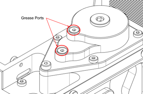
Maintaining adequate lubrication of the gears is vital for ensuring the product's longevity and seamless operation. Access to the grease ports is achievable by removing the hotzone shield and hopper assembly. As you turn the motor, administer silicone grease into these ports.
It's notable that the Pulsar Atom is pre-lubricated with silicone grease of NLGI viscosity grade of 2.
For a streamlined grease application, employing a compact grease gun, such as the Astro Mini Grease Gun, could prove beneficial.
# Periodic Inspection
For prolonged durability of the gearbox and its components, we advocate for routine thorough inspections and maintenance. It's prudent to regularly examine all gears and the housing. To facilitate this, detach the top cover from above to unveil the gears. Utilize towels to clear away the majority of the aged grease. Substitute any gears exhibiting significant wear marks or with diminished teeth.
# Hopper Venting Filter
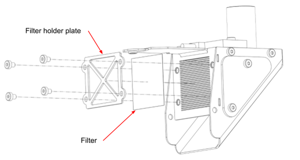
Utilizing the automatic pellet system entails the propulsion of pellets and dust through the system via compressed air. Over a period, polymer dust will accumulate within the filter, potentially causing an exhaust blockage. Such blockages can subsequently impair the feeding system. To prevent this, it's advisable to clean both sides of the filter periodically. This can be done by detaching the hopper (3 X M3 screws) and removing the filter holder plate (4 X M3 screws).
# Emptying the Hopper
Once pellets are lodged within the hopper, emptying it without spillage becomes a non-trivial task.
The alternatives at your disposal include either extruding the pellets until the hopper is entirely vacant, or employing a vacuum to extract the pellets through the inlet tube.
# Hotzone Removal
The hotzone can be removed for maintenance or troubleshooting purposes. To do this, you will need the following tools:
- 2.5mm allen key
- Heat Protection Gloves

Follow these steps for hotzone removal:
- Move the Z-axis upwards until the nozzle is at least 150mm away from the bed.
- Heat the hotzone to extrusion temperatures.
- Ensure the product is entirely free of any polymer by extruding it. Make sure the hopper is empty
- Power off the product and disconnect both the power and hotzone connectors.
- While the hotzone is still hot enough to contain molten polymer, unscrew the four M4 screws that join the coldzone and hotzone.
- Be prepared to hold the hotzone using heat protection gloves.
- You may need to gently pull on the heatzone to separate it from the extrusion screw.
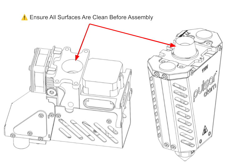
# Hotzone Installation
To install a heatcore, you will require the following tools:
- 2.5mm hex torque screwdriver
- Heat protection gloves
- Mild steel tweezers
- Heat gun
To perform the installation, follow these steps:
- Use a heat gun to heat the extrusion screw until the polymer becomes somewhat soft.
- Employ mild steel tweezers to remove any excess polymer that may protrude from the screw's flights, as this can hinder the screw from entering the barrel.
- Raise the Z-axis until the tip of the screw is at least 150mm above the bed.
- Connect the power and hotzone connectors.
- Position the heatzone over the bed and start heating it to extrusion temperatures.
- While heating, use mild steel tweezers to eliminate any polymer film that may have formed at the entrance of the barrel or case.
- Po wer off the product and disconnect both the power and hotzone connectors.
- While the hotzone is still hot enough to contain molten polymer, put on heat protection gloves and gently press the heatzone onto the extrusion screw. Be cautious, as polymer may extrude from the nozzle during this process.
- Once the heatzone is fully affixed to the coldzone, secure it in place using the four M4 screws. Initially, lightly torque the screws into position. Then, tighten them using a torque of 4.8Nm in an X-pattern to ensure uniform contact between the two zones. The following order is recommended:
# Screw Change
You can remove the extrusion screw for replacement or maintenance. Here are the tools you'll need:
- 2.0mm allen key
- 2.5mm allen key
- 4.0mm allen key
- Heat Protection Gloves
- Mild steel tweezers
- Heat gun
To accomplish this, please adhere to the subsequent steps:
- Follow the guidelines outlined in the "Heatzone Removal" section to detach the heatzone.
- Follow the guidelines outlined in the "Hopper Removal" section to detach the hopper.
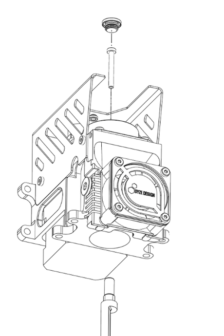
- Remove the threaded plug from the top cover.
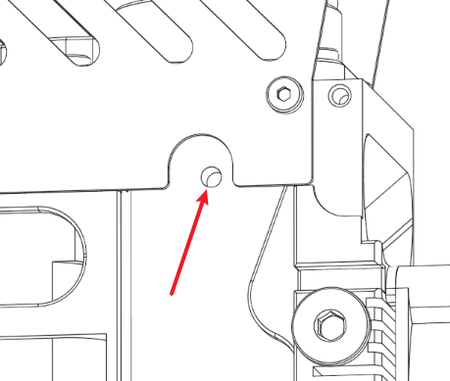
- Lock the screw's rotation by engaging the stepper motor or inserting a 3mm shaft into the hole located on the side of the main case.
- Unscrew the M3 screw that secures the extrusion screw in place.
- Carefully remove the screw.
- When installing the new screw, ensure it is correctly inserted into the shaft coupler before tightening the M3 screw.
- Follow the instructions provided in the "Heatzone Installation" section to reattach the heatzone.
# Nozzle Change
The nozzle of the Pulsar Atom can be readily removed when needed. To achieve this, please follow these steps:
- Torque wrench
- 20mm hex socket
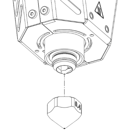
To do so you need to:
- Heat the bottom section to near polymer melt temperature. (For example: 160°C for PLA)
- Power off the product.
- Unscrew the nozzle.
- Remove any excess polymer from the barrel, the screw and the nozzle.
- Ensure that the conical surfaces on the barrel and nozzle are clean, as they ensure proper sealing.
- When the extruder is under 50°C, install the new nozzle by applying a torque of 14Nm. (Do not exceed 15Nm)
# Purging
Purging Compound consists of inert material used to clean the Extruder.
General purpose is used in low temperature applications to switch between resins, remove corrosive materials for regular downtime & lightly clean the extrusion screw & barrel.
High temperature is used to clean and flush out engineering material. It’s also useful as a step up to engineering material from low temperature resins or step down from engineering material.
Heavy Scrubbing is used for a deep clean of the extruder. It’s useful to flush burnt or carbonized material to an extent. This needs to be paired with a common purge afterwards.
INFO
Dyze Design is distributor of Asaclean® U Grade and Asaclean® Ex Grade. Contact our sales team to purchase purging material or get more information.
Here are the steps to follow to purge the hotzone:
- Empty the Pulsar’s hopper
- Flush the barrel using the extrusion command
- Fill the hopper with 50-100 grams of purge
- Bring the Pulsar’s to purging temperature (Warning : make sure it’s compatible with the previous resins temperature range)
- Extrude until there’s no previous material mixed in the purge
For material change, you might follow the following steps:
- Empty the bulk and Pulsar’s hopper
- Flush the barrel using the extrusion command
- Fill the Bulk hopper with new material
- Bring the Pulsar to set temperature (Warning : make sure it’s compatible with the previous resins temperature range)
- Extrude until there’s no previous material mixed
# Pellet Sensor Calibration Procedure
The sensor is capacitive, meaning that it doesn’t need specific material to operate. However, different materials may need different sensor settings. Here's a few steps on how to adjust your sensor.
Tools Needed :
- Flat screw driver
Steps to follow:
- Power on the pellet feeding system without compressed air
- The sensor needs to be screwed in place and be flush with the inside wall
- Fill the Pulsar™ Atom hopper with material
- Use a small flat screwdriver to turn the potentiometer counterclockwise. Stop when it doesn’t detect. It should open the solenoid valve and give a faulty alarm after a few seconds.
- Make a half turn clockwise and you're done!
# Dehumidifying Maintenance Routine
Diagnosing the Problem
To diagnose the insulation, use a multimeter set to 200MΩ. Measure the resistance between one of the heater's power cables and the ground. A healthy reading should be above 1MΩ or show an "Open Circuit" reading.
If you get a low resistance reading, it's most likely due to moisture. This is a common issue that you can resolve by gently drying the heater.operating temperature.
The Drying Process
Follow these steps to safely remove moisture from the heater:
Turn on the printer and set the hot end temperature to 50-75°C. The goal is a gentle, sustained warmth. Maintain this temperature for at least 2 hours to allow the moisture time to fully evaporate.
Next, increase the hot end temperature to 95°C and hold it there for at least 2 more hours.
Use your multimeter to check the resistance again. When the multimeter shows an "open circuit" or "OL" reading, the heater is dry.
Once the heater is dry, you can safely run it at its normal operating temperature.
# Risk Assessment
A full risk assessment document is available for the Pulsar™ Atom. This document states which inherent risks remain for the operation of the extruder. Trained personnel using this machinery are required to familiarize themselves with the assessment.
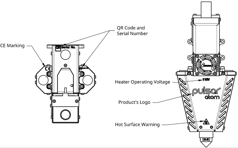
# Pulsar™ Atom Extruder authenticity and informative markings
A genuine Pulsar™ Atom Extruder will have permanent markings etched on the front Hotzone shield, on the top of the Coldzone shield and on the Barrel Plate. A complete Pulsar™ Atom consists of 2 serial numbers. One for the Coldzone Shield and one for the Barrel Plate.