# Horizon™ Auto-bed leveling (ABL) sensor
# First setup of your Horizon™ bed leveling sensor
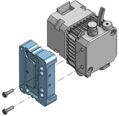
- Mount the Horizon on the extruder
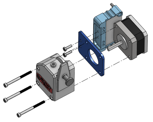
The Horizon is compatible with many types of extruders. This ABL sensor is designed for light extrusions systems. See the "Mounting" section of the present document and follow the instructions related to your specific extruder. For the DyzeXtruders, simply use the provided M3x0.5x10 screws to mount the sensor as shown.
WARNING
The HoriZon is a delicate device designed with precision. Applying forceful impacts may cause breakage. Exercise caution during HoriZon setup, ensuring a trial run in mid-air before surface contact with your bed. Avoid using an extruder exceeding the specified maximum weight to prevent damage or breakage. See the Specification Table below for more details.
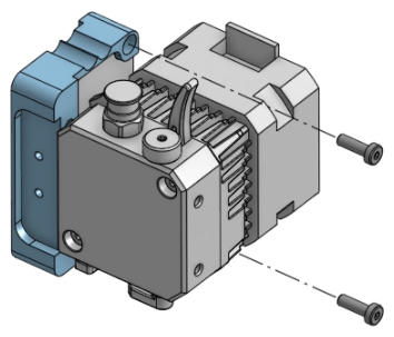
- Mount the Horizon on the carriage
Use the provided M3x0.5x10 screws to mount the Horizon on the Carriage. For information on the mounting holes locations, see the "Mounting" section of the present document
WARNING
Make sure the mounting holes of your carriage are well positioned as a hole offset might induce deformation in the Horizon bracket, which might affect the accuracy of the device. For best performances, the HoriZon should be mounted on a metal bracket. However the use of an other material is still acceptable.
- Power the Horizon
Using the provided cable, connect the top connector of the Horizon to the Z endstop pins of your motherboard (for general purpose digital signal). Refer to the "Wiring" section of the present guide for further details. If you would prefer an analog output, refer to the "Analog output" section of the present guide for the setup instructions.
WARNING
Make sure the wire path runs far enough from all electrical noise sources (motors, drivers, fans, …). That should avoid wrong detection during homing.
WARNING
Make sure the wires respect the connection pinout.
WARNING
Make sure the wires are not live while connecting them.
- Configure the firmware
Follow the "Firmware configuration" part of this guide for the configuration of the Horizon using Marlin or Duet (more firmware guides will be added in the future).
- Level your bed
One of the main advantages of the Horizon is being able to do a mesh leveling of your bed using the tip of your nozzle as a probe before every print.
However, if you prefer the "old school" way of doing it, follow these steps:
Bring your extruder over a corner of your bed and home your system in Z. The Z value should now be in the negatives (due to the Z offset set up in the firmware section).
Lift your extruder back to 0.
Level your bed as you would normally do with the good old "sheet of paper" method.
Move to another corner and repeat the last step.
Repeat until the bed is perfectly leveled.
Stay leveled!
Your sensor is now ready to use. No matter the future changes you make to your bed, extruder or carriage, the Horizon sensor will always home perfectly and safely.
WARNING
Always ensure your nozzle is plastic free before z axis homing. Residual plastic stuck to the tip of the nozzle could add an extra offset.
- Experiment!
The second connector provides an analog signal proportional to the force measured by the Horizon. You could for instance use it to control or monitor the vertical forces applied to your carriage assembly. This could in theory be used to correct the layer height in real time. The signal could also be connected to an analog to digital converter (ADC). This is a great tool for the tinkerer!
# General
# How it works
The Horizon, for all practical purposes, transforms your nozzle into a very sensible force sensor. This permits very accurate Z homing of your bed without any risk of damaging your printer as the Z motors will be stopped the instant your nozzle touches the bed.
# Specifications
| Specifications | ||||
|---|---|---|---|---|
| Min | Typical | Max | Unit | |
| Voltage | 3.3 | 5 | 6 | V |
| Current | 15 | 28 | 35 | mA |
| Output logic | 3.3 | High/low | 6 | V |
| Output analog | 0 | 3 | V | |
| Detection force | 0.69 | N | ||
| Temperature | 0 | 21 | 40 | ℃ |
| Mounting hole | M3 | mm | ||
| Extruder Weight | 500 | g |
Output table:
| Contact on the bed detected | Logic | Red LED |
|---|---|---|
| NO | HIGH (Vin) | OFF |
| YES | LOW (0V) | ON |
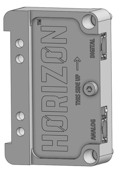
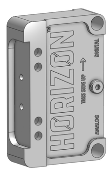
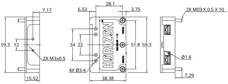
Labels and indicators:
- The straight arrow indicates the upwards direction.
- The "DIGITAL" label indicates which connector outputs a digital signal (switch type)
- The "ANALOG" label indicates which connector outputs an analog signal (real-time reading of the vertical force applied on the nozzle)
- The LED indicates power and contact with the bed. A red LED indicates contact with the bed. See the preceding "Output table" for better understanding.
WARNING
As the HoriZon will still be powered between homings, it will continue sending signals even during a print. Thus, it is normal to see the signal LED flash. The firmware is configured to ignore these signals between homings.
# What's included
| Item | Quantity |
|---|---|
| Horizon sensor | 1 |
| Extruder Mounting Bracket | 1 |
| Cable (1 meter) | 2 |
| Mounting hardware (M3x10 screws, M3x6 screws) | 2 |
# What's required
- A compatible 3D printer controller
- With proper firmware version (refer to the firmware configuration section of the present guide).
- A mounting bracket (metal preferred, other materials still acceptable).
WARNING
Make sure your extrusion system (extruder and hotend) meets the requirements in terms of weight. See the Specification Table below for more details.
# Mounting
The Horizon should be attached to both the carriage and the extruder (or hot end, on a bowden setup). It should be the only link between the two.
# Mounting the Horizon to your extruder
The Horizon is compatible with different types of extruders. For the DyzeXtruder , simply use the provided M3x0.5x10 screws to mount the sensor as shown.
The E3D Hemera is mounted very similarly to the DyzeXtruders. Be mindful to use the provided shorter M3x0.5x6 screws to mount the sensor to the side of the motor, as longer screws can damage the Hemera extruder..
For the BondTech BMG extruders, it is necessary to use the provided bracket. The bracket is to be inserted between the extruder and the motor and attached to the Horizon frame using the provided M3x0.5x10 screws as shown.
# Mounting the Horizon to your carriage
Use the provided M3x0.5x10 screws to mount the Horizon on the Carriage. For information on the mounting holes locations, see the following drawing.
WARNING
Make sure the carriage does not come in contact with the extruder or the hot end (on a bowden setup). The extruder (and by association the motor and the hot end) should be entirely supported by the Horizon.
WARNING
Make sure the mounting holes of your carriage are well positioned as a hole offset might induce deformation in the Horizon bracket, which might affect the accuracy of the device. For best performances, the HoriZon should be mounted on a metal bracket. However the use of an other material is still acceptable.
# Wiring
| Cable Color | Connection |
|---|---|
| Black | Ground |
| Blue | Signal |
| Red | +5V |

# Pins
Most endstop pins will have the same 3 pins, and sometimes only Signal and Ground. If you only have these two, there should be a 5V or 3.3V somewhere else on your main board.
It is also possible to use the following pins:
- Expansion pins
- Communication pins
For the use of these pins, some boards are very limited and a deeper understanding is required for connecting the Horizon properly.
For pins location examples, refer to the Connections examples of our Sentinel support page, since the Sentinel uses the same pins.
# Connection Examples
(digital output configuration)
# Duet boards
# Duet 2
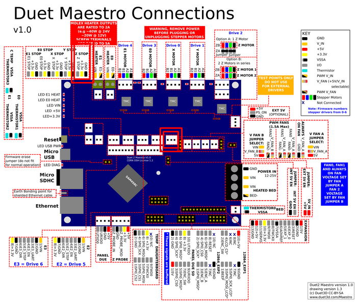
The signal output of the Horizon should be connected to the Z endstop. See the Duet 2 Maestro pinout below for a red highlight of the specified pins.
# Duet 3
On a Duet 3 mainboard, you can plug your Horizon on one of 9 IO headers provided.
Be careful of the pinout (see image below).
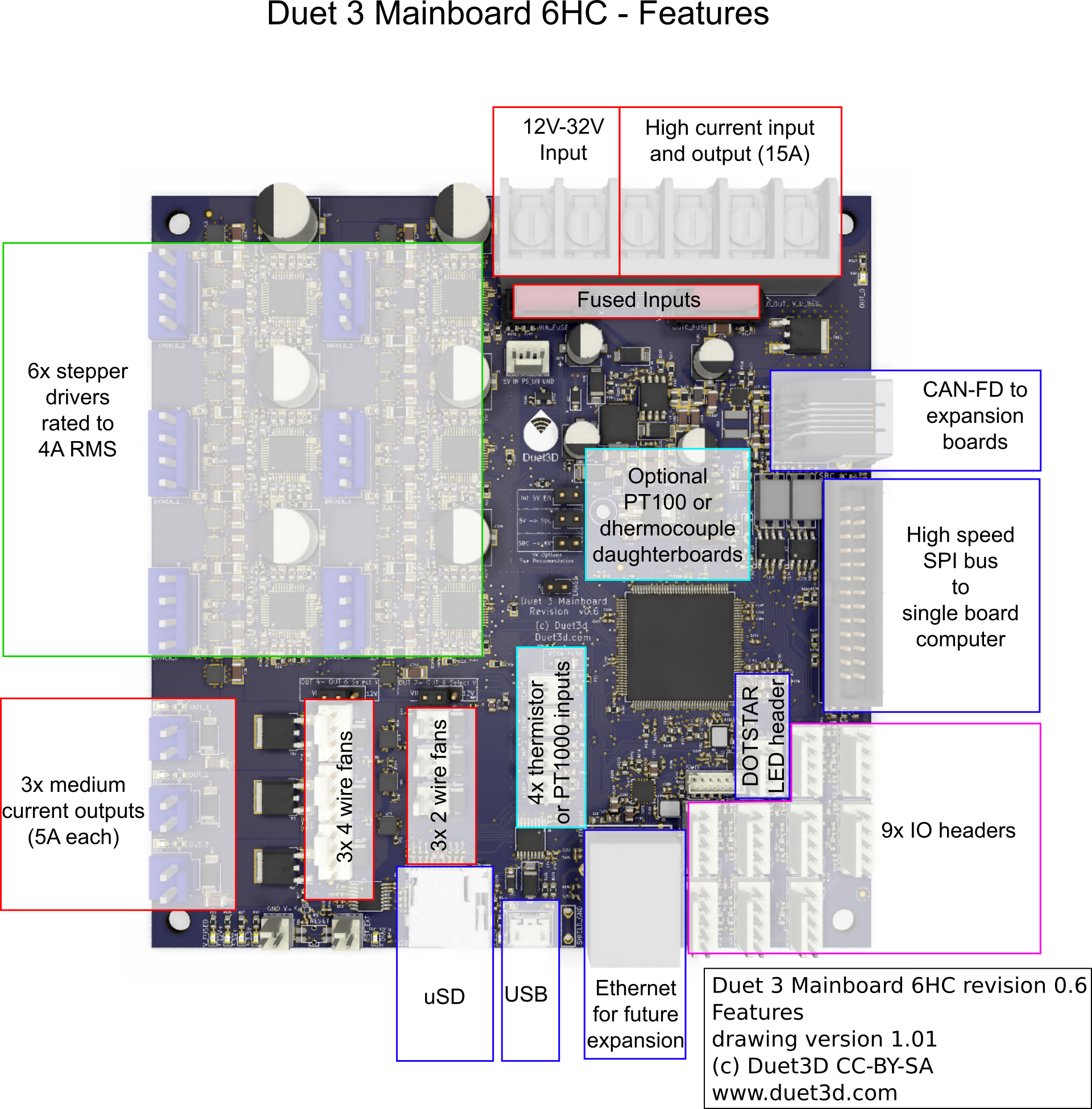
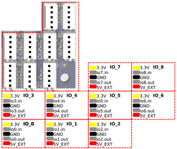
Per example, if you were to plug the HoriZon in IO_3, The signal wire (blue) would be connected to "io3.in", the power wire (red) would be connected to "3.3V" and the ground wire (black) would be connected to "GND".
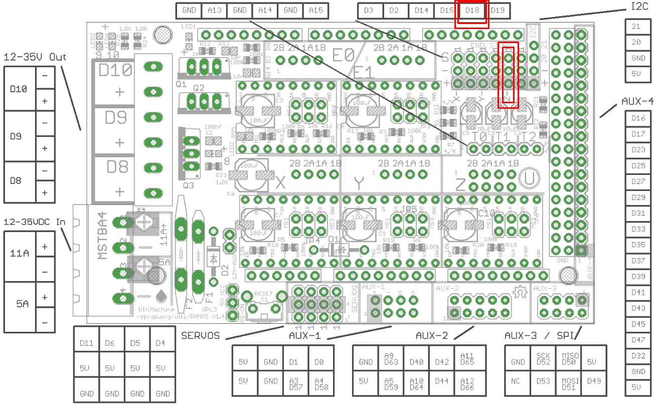
# Ramps 1.4
See the Ramps 1.4 pinout below for a red highlight of the pins to connect.
# Firmware configuration
# Marlin Firmware Version 2.1.2
# Basic configuration Digital output - Manual leveling
The Horizon can be used as a basic z axis endstop switch.
If so, follow these configuration steps in Configuration.h:
- Find and comment out this line:
#define USE_ZMIN_PLUG //Uncomment by removing "//"
- Set direction of the endstop when homing
Z_HOME_DIRto-1.
#define Z_HOME_DIR -1 //Uncomment by removing "//" and change value to -1.
- Set the following values to
trueto invert the logic of the "z min probe". The output signal of the Horizon is logichighwhen idle.
#define Z_MIN_ENDSTOP_INVERTING true //Uncomment by removing "//" and change value to true
#define Z_MIN_PROBE_ENDSTOP_INVERTING true //Uncomment by removing "//" and change value to true
- Find and comment out:
#define Z_MIN_PROBE_USES_Z_MIN_ENDSTOP_PIN //Uncomment by removing "//"
- To avoid homing with a Z probe outside the bed area, Z safe homing has to be enabled. Comment out the following line:
#define Z_SAFE_HOMING //Uncomment by removing "//"
By default, x and y coordinates of z safe homing is the center of the bed.
Ensure that you don't have any screw holes or bed irregularities at this point.
If so, you can change coordinates by updatingZ_SAFE_HOMING_X_POINTandZ_SAFE_HOMING_X_POINTvalues.Set homing feed rates:
#define Z_PROBE_FEEDRATE_FAST (4 * 60) //Uncomment by removing "//" and change value
#define Z_PROBE_FEEDRATE_SLOW (Z_PROBE_FEEDRATE_FAST / 2) //Uncomment by removing "//" and change value
TIP
Horizon is the most accurate when homing feedrate is set between 1 to 4 mm/s.
- Marlin allows the user to do multiple probing. It may improve results by averaging. Find and comment out:
#define MULTIPLE_PROBING 2
#define EXTRA_PROBING 1
- Finally, ensure that the nozzle to probe offsets for x and y axis are set to
0as the nozzle is actually the probe. Find and comment out:
#define NOZZLE_AS_PROBE
#define NOZZLE_TO_PROBE_OFFSET {0, 0, Z}
TIP
For now, set the z value to 1. This value will need to be calibrated to your system. Every printer is different. Some carriages may have more wobble than others. Some may use stiffer bed springs than others. This value will need to account for all of that, but for now a 1 value will work.
WARNING
If replacing another bed leveling probe, be sure to comment any line enabling the old sensor as failing to do so will cause a compiling error due to there being 2 bed leveling probes active at once.
- Flash the firmware.
# Find your Z value
Your Horizon should now be mostly operational. You only need to obtain the right "z" value for your system.
- Heat your bed and nozzle to the expected printing temperature.
WARNING
Before the first z homing, ensure the z min endstop status changes when a little force (by hand for example) is applied on the nozzle. You can send a M119 command to report the status. This would prevent the nozzle from smashing through the bed and damaging your printer if ever the Horizon wasn't set up properly.
With your printer being hot, home your system in Z. Your reported nozzle height should now be 0 and the nozzle should hover a bit higher than the bed because of the z offset of 1mm.
Enter the
M211 Z0 S0command to disable the Z min endstop.
TIP
With the manual control of your printer, decrement the z height by the minimal value possible until your nozzle is at your preferred height for printing (using, per example, the sheet of paper calibration method). Once you reach the perfect height, note the actual z value (it should be in the negatives). Take that value and add 1. This calculated value will be your real z offset value.
For instance, if the paper sheet method brings you to a Z height of -0.3, your real z offset value will be 0.7.
Enter the
M211 Z0 S1command to enable the Z min endstop.In your firmware, set the
NOZZLE_TO_PROBE_OFFSET"z" value to the value previously calculated. The value should be in the positives.
TIP
You can also manually enter the following M851 Zz command where z is the previously calculated NOZZLE_TO_PROBE_OFFSET "z" value, followed by an M500 command to store the settings to EEPROM.
WARNING
Please note that the z value may need a bit of tweaking during your first prints to obtain the perfect leveling every time.
# Auto bed leveling Digital output - ABL
The Horizon transforms your nozzle into a probe you can use to auto level your bed. In this way, you are able to compensate for an uneven bed by adjusting nozzle height during printing. ABL is configured in Configuration.h.
Follow the previous Basic Configuration setup to set a couple of parameters correctly.
Find and comment out:
#define Z_SAFE_HOMING
- You can choose one of the options of auto bed leveling that Marlin provides by uncommenting it:
#define AUTO_BED_LEVELING_3POINT

#define AUTO_BED_LEVELING_LINEAR

#define AUTO_BED_LEVELING_BILINEAR

#define AUTO_BED_LEVELING_UBL

#define MESH_BED_LEVELING
- Depending on which option you choose, you might set a grid max point for x and y axis.
WARNING
Make sure that each grid point doesn't coincide with screw holes or any bed irregularities.
TIP
For further information on auto bed leveling, you can reach the following URL :
https://marlinfw.org/docs/features/auto_bed_leveling.html (opens new window)
- Once options and parameters are set, you can start an automatic bed leveling sequence with
G29command and save mesh values into EEPROM withM500command.
# RepRap Firmware Version 3.3
# Basic configuration Digital output - Manual leveling
In config.g file, add the M574 to set the endstop configuration:
M574 Z1 S2 P"!XXX"
Where "XXX" is the pin name the signal connector of the HoriZon is plugged into (see the official pinout document of your current motherboard to determine the pin names). Per example, if the HoriZon was connected to the io3.in input pin of the Duet mainboard, the command would be:
M574 Z1 S2 P"!io3.in"
S2 parameters means that the Horizon acts as a Z probe.
WARNING
Don't forget the ! before the pin name as the Horizon is an active low.
In the same config.g file, add the M558 command to set the z probe type:
M558 P5 C"!io3.in" H1
The P5 parameters means that the Horizon acts as a switch for bed probing.
In this example, the Horizon detection signal is plugged in the io3 input pin of the Duet mainboard.
WARNING
Don't forget the ! before the pin name as the Horizon is an active low.
The H1 parameters means that the Z probe dive height is set to 1 mm. This is the height to travel between each probing when auto bed leveling is running. This value could be larger for an uneven bed but it will make the probing slower.
At this point, you can confirm that your configuration is well done by checking the Z probe status. When a little force towards the nozzle is applied (with your finger for instance), you should see the Z probe status value move to 1000. This is a recommended step before running a real z homing and potentially damaging the bed.
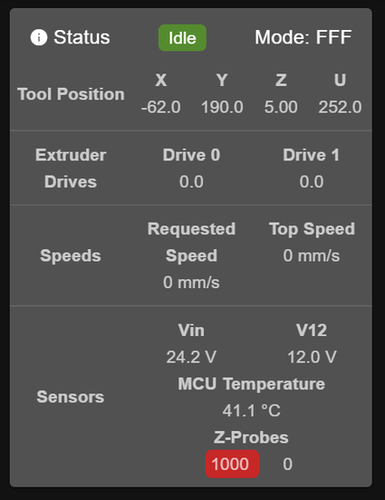
In this example, you can see on the Duet Web Control that the Horizon mounted on the first tool is triggering.
In config.g file, add the G31 command to set probe offset (you must add the G31 line command after the M558 one):
G31 P500 X0 Y0 Znnn
This is the minimum G31 configuration. As the nozzle is the probe, X and Y offset are set to 0.
P500 is the default trigger value and it corresponds to a logic high level value.
The Znnn value will need to be calibrated to your system. Every printer is different. Some carriages may have more wobble than others. Some may use stiffer bed springs than others. This value will need to account for all of that, but for now a 1 value will work.
You can also set a different acceleration for the homing sequence with the M201.1 command. By reducing the acceleration during homing, you prevent false detection.
WARNING
Before the first z homing, ensure the z min endstop status changes when a little force (by hand for example) is applied on the nozzle. You can send a M119 command to report the status. This would prevent the nozzle from smashing through the bed and damaging your printer if ever the Horizon wasn't set up properly.
To home the z axis, use the G30 command in homez.g and homeall.g files. Your nozzle will stop at the height you specified in the H parameter of M558 command after probing is done.
TIP
To obtain the right Znnn value offset in G31 command for your system, follow these steps (based on Test_and_calibrate_the_Z_probe (opens new window)) :
Heat your bed and nozzle to the expected printing temperature.
Enter
M564 H0 S0to disable axes limit.With your printer being hot, home your system in Z. Your reported nozzle height should now be
0and the nozzle should hover a bit higher than the bed because of the z offset of 1mm.Enter
M564 H1 S1to re-enable axes limit.With the manual control of your printer, decrement the z height by the minimal value possible until your nozzle is at your preferred height for printing (using, per example, the sheet of paper calibration method). Once you reach the perfect height, note the actual z value (it should be in the negatives). Take that value and add
1. This calculated value will be your real z offset value.
Per example, if the paper sheet method brings you to a Z height of -0.3, your real z offset value will be 0.7.
# Auto bed leveling Digital output - ABL
For auto bed leveling, follow the previous (Basic Configuration)[#basic-configuration-2] setup to set a couple of parameters correctly.
Use the M557 command to define G29 mesh grid:
M557 X8:155 Y10:185 P3:3 ;for a 9 probing points mesh.
When you're satisfied with the probing points, you can run the G29 (after all axis have been homed) command to start the mesh leveling.
Save or load the height map file with the corresponding S parameters.
G29 Snnn
# Klipper Firmware
# Basic configuration
In printer.cfg file, you can add a new section [probe]:
[probe]
pin: !XXX
x_offset: 0.0
y_offset: 0.0
z_offset: 0.0
speed: 5.0
Where "XXX" is the pin name the signal connector of the HoriZon is plugged into. In klipper, pin definition is the same as the mcu one. So you have to know which microcontroller you are using to identify the pin you connect to the Horizon.
For example, Makerbase MKS Gen L board Z pin is connected to the PD3 pin of the MCU. The pin definition line would then be:
pin: !PD3_
WARNING
Add ! before pin name as the Horizon triggers on logic low.
The z_offset parameter depends on the temperature of the system, the wobble of the carriage and the springiness of the bed.
In order to determine the right z_offset for your system, follow the following procedure:
For now, set the
z_offsetvalue to1. This value will need to be calibrated to your system. Every printer is different.For this calibration, setting the printer's Z
position_minto-5is temporarily necessary.Flash the firmware. Your Horizon should now be mostly operational. You only need to obtain the right
z_offsetvalue for your system:- Heat your bed and nozzle to the expected printing temperature.
WARNING
Before the first z homing, ensure the z min endstop status changes when a little force (by hand for example) is applied on the nozzle. You can send a
M119command to report the status. This would prevent the nozzle from smashing through the bed and damaging your printer if ever the Horizon wasn't set up properly.With your printer being hot, home your system in Z. Your reported nozzle height should now be
0and the nozzle should hover a bit higher than the bed because of the z offset of1mm.With the manual control of your printer, decrement the z height by the minimal value possible until your nozzle is at your preferred height for printing (using, per example, the sheet of paper calibration method). Once you reach the perfect height, note the actual z value (it should be in the negatives). Take that value and add
1. This calculated value will be your real z offset value.
Per example, if the paper sheet method brings you to a Z height of
-0.3, your real z offset value will be0.7.Set the printer's Z
position_minback to0.In your firmware, set the
z_offsetvalue to the value previously calculated.
TIP
Other parameters can be used for other purposes, you can refer to the klipper documentation (opens new window)to get a closer look at them.^
In [stepper_z] section, you must change endstop_pin parameters:
[stepper_z]
endstop_pin: probe:z_virtual_endstop #find this line
Finally, it is better to add [safe_z_home] to move the toolhead in a known position on the bed without damaging the printer:
[safe_z_home]
home_xy_position: 100, 100
#   A X, Y coordinate (e.g. 100, 100) where the Z homing should be
#   performed. This parameter must be provided.
#speed: 50.0
#   Speed at which the toolhead is moved to the safe Z home
#   coordinate. The default is 50 mm/s
z_hop: 1
#   Distance (in mm) to lift the Z axis prior to homing. This is
#   applied to any homing command, even if it doesn't home the Z axis.
#   If the Z axis is already homed and the current Z position is less
#   than z_hop, then this will lift the head to a height of z_hop. If
#   the Z axis is not already homed the head is lifted by z_hop.
#   The default is to not implement Z hop.
# Auto bed leveling
Once you're done with the basic configuration of the Horizon, you can add a [bed_mesh] section to the printer.cfg file. This module may be used to compensate for uneven bed surface.
[bed_mesh]
speed: 50
horizontal_move_z: 10
mesh_min:20,50
mesh_max:170,200
probe_count: 3,3
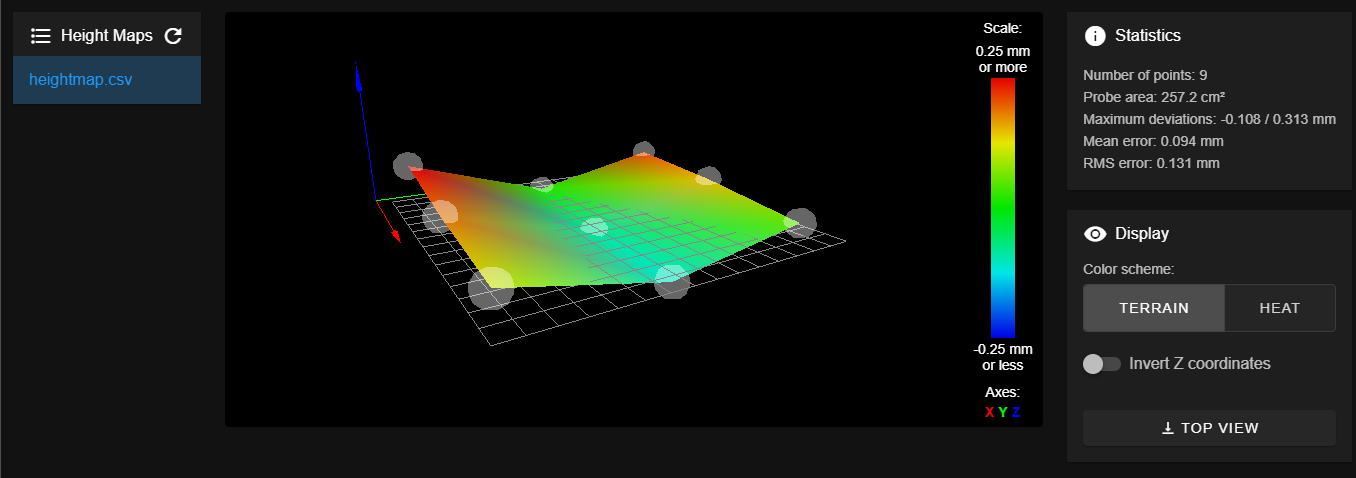
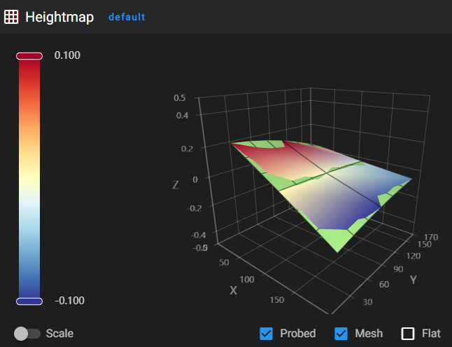
Once you're satisfied with the bed_mesh module configuration, you can run the G29 command to start a mesh bed calibration. Results can be found in the Heightmap menu of your web interface:
# Troubleshooting
If probing seems unreliable or if the Horizon starts to trigger due to the following reasons :
- On z axis direction change
- Carriage or axis vibration
First, ensure you followed the first setup steps.
Check if the Horizon is well tightened on the carriage. Be careful of the power cable condition. Check loose connections on both sides of the cable.
You can also reduce acceleration of the z axis to reduce possible false detection when homing/leveling.
In Marlin, you can also disable fans, heaters and/or stepper and add an extra delay before probing. This can minimize electrical noise and improve probing precision:
//#define PROBING_HEATERS_OFF

//#define PROBING_FANS_OFF

//#define PROBING_STEPPERS_OFF

//#define DELAY_BEFORE_PROBING 200
WARNING
Do not remove the top cover of the HoriZon. Doing so and reinstalling the top cover incorrectly may reduce the accuracy of the system or make it unusable.
If the top cover of the HoriZon was removed at any time during its life cycle, it is necessary for the good function of the product to reinstall it following this procedure:
Install the top cover on the HoriZon using the provided M03x0.5x04 screw. Do not tighten the screw.
Insert a 0.15mm thick spacer between the top cover and the top wall of the HoriZon. Be careful not to damage the liquid tape protecting the strain gauge.
Tighten the M03x0.5x04 screw. Do not overtighten the screw as to make it impossible to remove the spacer.
Remove the spacer.
# Analog output Experimental
The Horizon provides an analog output proportional to the force applied on the nozzle. You can expect to have a sensitivity between 0.35mV/g to 0.6mV/g.
Reprap firmware have an analog mode (mode #1) you can select during z-probe configuration. The detection threshold value can be configured with the Pnnn parameters of the G31 command.
The analog output could be used in other contexts where you would need a sensitive force sensor. You can plug it into the input of an analog to digital converter (ADC) and monitor the force with an external controller.
WARNING
As the analog output is not mandatory to properly use the Horizon, we offer it as an experimental feature. You are free to calibrate it yourself with a weight scale to get a precise sensitivity.