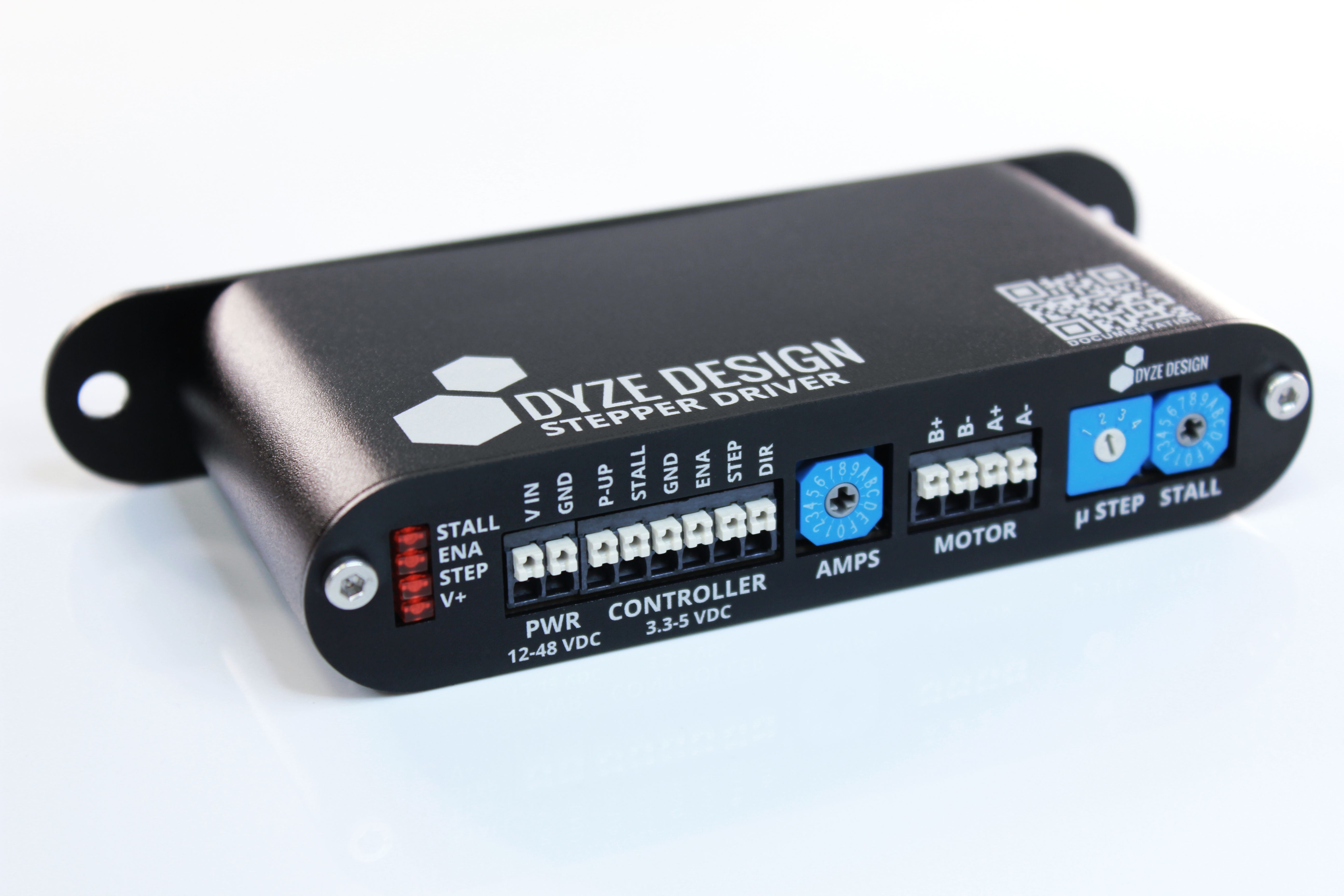
# Stepper Driver
# What's included
| Item | Quantity |
|---|---|
| Dyze Stepper Driver | 1 |
| M4x10 screw | 2 |
| DIN Rail (optional) | 1 |
# What’s required
- A compatible 3D printer controller
- With proper firmware version (refer to “Firmware configuration”).
- Stepper Motors
WARNING
The Dyze Stepper is optimized for motors up to 6A and can handle 12V to 48V supply voltage.
# First setup of your Dyze Stepper
1. Mount the Dyze Stepper
The Dyze Stepper Driver can be mounted using 2 M4 screws. The Dyze Stepper offers a DIN rail support.
2. Set the desired microstepping
Refer to the “Microstep Configuration” section of the present guide for further details.
3. Set the motor current
Adjust the driver current with the rotary switch according to your rated motor current. This setting allows better performance and efficiency for the motor.
If you want to use the stall detection feature, the current setting must be set properly before setting the stall detection level.
Refer to the “Current Configuration” section of the present guide for further details.
4. Some wiring
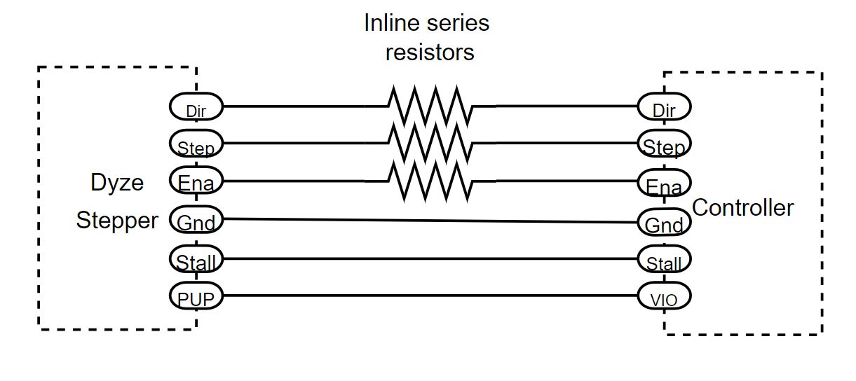
Made the appropriate connection between the motherboard and the DyzeStepper for control signals (Step, Dir, Enable, Stall and ground). The minimum configuration requires 4 wires (if stall detection is not used).
Connect a 4 wires motor to the DyzeStepper. Make sure to connect the wires BEFORE applying power to the DyzeStepper.
Refer to the “Hardware configuration” section of the present guide for further details.
WARNING
If your control signals are higher than 5V don’t forget to add a serie resistor on all the control signals (dir, ena and step)
5. Power the Dyze Stepper
Once all the required wiring is done, connect a power supply to the power connector. Be careful of the polarity. The driver will work with voltages between 12V and 48V.
Refer to the “Hardware configuration” section of the present guide for further details.
6. Configure the firmware
Refer to the “Firmware configuration” section of the present guide for further details.
7. Configure the stall switch
WARNING
To achieve optimal current management performance with the stepper driver, it's essential to configure the stall switch correctly.
The stallguard feature is closely linked to the coolstep feature. Coolstep is employed to regulate the current supply, ensuring that the stepper motor receives precisely the required current. Serving as the current management mechanism, coolstep adjusts the current according to the necessary torque, thus enhancing the motor's performance while concurrently reducing energy usage and heat generation.
To properly configure the stall switch, refer to the “Stall switch configuration” section.
8. Experiment with the stallguard!
The controller connector provides a stallguard digital active low output pin, this signal could be used to detect motor stall or it could be used as an endstop switch.
# Typhoon/Pulsar Quick Start
Here are the recommended configurations for use with Dyze Design's Typhoon and Pulsar:
# Dyze Stepper switches positions
| Switch | Position |
|---|---|
| Amps switch | 8 |
| uStep Switch | 2 |
| Stall switch | 1 |
# Motor connections
WARNING
Wiring order can vary from one product to another. When polarity is reversed (Pairs A ←→ Pairs B), the motor will rotate in reverse direction. Always prioritize the product documentation.
| Connection | Cable |
|---|---|
| B+ | Green |
| B- | Black |
| A+ | Red |
| A- | Blue |
# Pulsar Atom/Zephyr Quick Start
Here are the recommended configurations for use with Dyze Design's Pulsar Atom or Zephyr Extruder:
| Switch | Position |
|---|---|
| Amps switch | 3 |
| uStep Switch | 2 |
| Stall switch | 1 |
# Motor connections
| Connection | Cable |
|---|---|
| B+ | Green |
| B- | Black |
| A+ | Red |
| A- | Blue |
# Duet configuration
;;;;;;;;;;;;;;;;; DRIVE MAPPING ;;;;;;;;;;;;;;;;;;
M584 X- Y- Z- Ex			  ; The pulsar drive is mapped to Drive X
M350 X-- Y-- Z-- E16 I1 		; 16 Microstepping with interpolation enabled, to customize

;;;;;;;;;;;;;;;; DRIVE DIRECTION ;;;;;;;;;;;;;;;;;
M569 Px S0 R1 T2		; Drive X goes backwards
With the wiring example below, the argument Ex would correspond to E2, and the argument Px would be equal to P2.
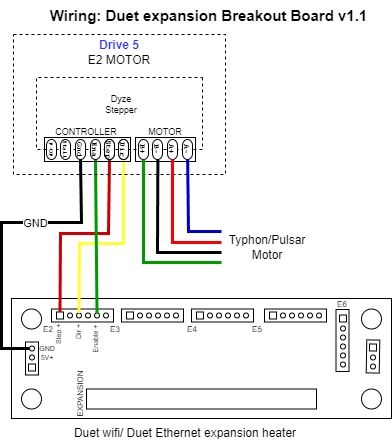
# Duet wiring example
To utilize the Dyze stepper with a Duet board, it's necessary to incorporate the Duet 2 expansion Breakout Board.
# General
# How it works
The DyzeStepper is equipped with a Trinamic™ controller and it works like a standard stepper driver, but with better efficiency, performances and more features.
# Specifications
| Min | Typical | Max | Unit | |
|---|---|---|---|---|
| Vin | 12 | 24 | 48 | V |
| Current | 0,9 | - | 6 | A |
| Power | 10 | - | 288 | W |
| Input Voltage (P-UP) | 3.3 | - | 48 | V |
| Controller inputs pins | 3.3 | 5 | 48 * | V |
| Recommended operating temperature range | 15 | 21 | 30 | ℃ |
WARNING
To use higher than 5 volts signal voltage, inline series resistors must be added.
| 12V | 24V | 48V |
|---|---|---|
| 680Ω | 1.5KΩ | 2.7KΩ |
# Hardware configuration
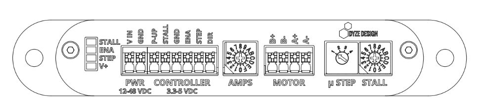
The connectors on the DyzeStepper are screwless terminals. That means that you only need to insert the wires into the connector or push the white button to unload the wire.
The compatible wire sizes are 16 to 24 AWG. Stranded wire or solid wire, both will work, but we highly recommend solid wire or crimps with stranded wire. It gives the best contact solution especially for high current rated applications.
# Dyze Stepper Typical Wiring Scheme
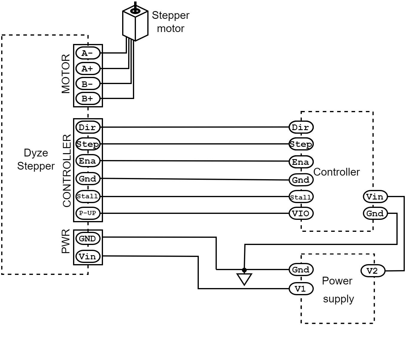
# PWR and CONTROLLER connectors
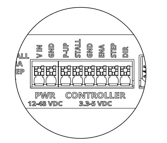
PWR - power supply connector
| VIN | GND |
|---|---|
| +12 to +48 VDC | Power ground |
CONTROLLER - driver communication inputs and output connector
| P-UP | STALL | GND * | ENA ** | STEP ** | DIR ** |
|---|---|---|---|---|---|
| Stallguard pin supply voltage from the controller (3.3V to 48V) | Stallguard logic output, Active low*** | Signal ground, must be connected to the controller ground | Enable input (optional) Stepper will be active when left unconnected 3.3V to 5V | Step/pulse input 3.3V to 5V | Direction input 3.3V to 5V |
WARNING
This ground must never be used to power the unit
WARNING
If you have to connect the stepper to higher control voltages, inline series resistors must be added.
| 12V | 24V | 48V |
|---|---|---|
| 680Ω | 1.5KΩ | 2.7KΩ |
TIP
This pin drives LOW when a stall has been detected. Otherwise, it outputs the P-UP voltage. If the stallguard™ is used, the user has to connect this pin to the controller input I/O voltage.
# MOTOR - stepper motor output connector
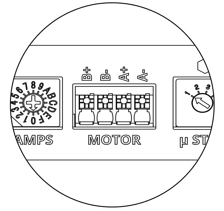
| B+ | B- | A+ | A- |
|---|---|---|---|
| Phase B, positive output | Phase B, negative output | Phase A, positive output | Phase A, negative output |
Stepper motor wires colors are usually as follows: Red ( A+ ), Blue ( A- ), Green ( B+ ), Black ( B- )
# Light indicators
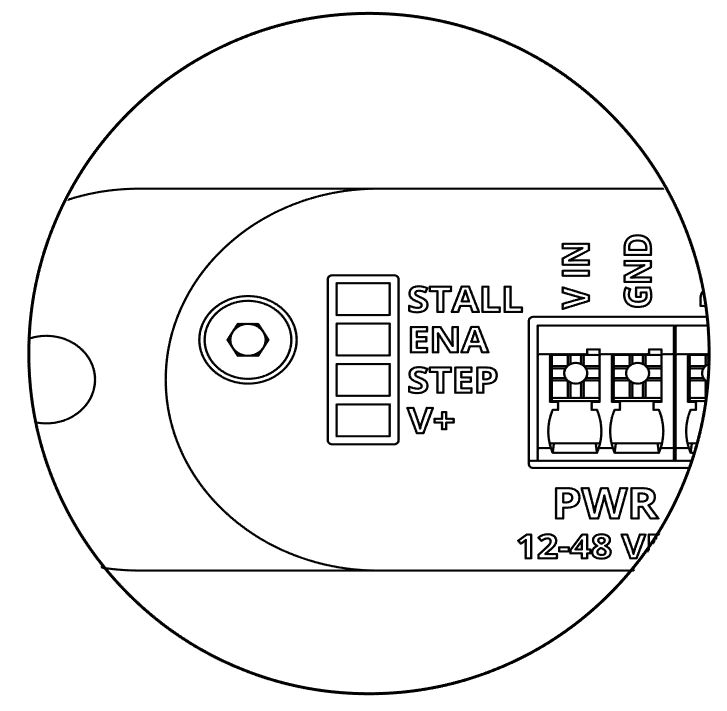
Use the stacked LEDs to monitor the basic functionalities of the driver.
| STALL | ENA | STEP | V+ |
|---|---|---|---|
| This light will turn ON when the driver detects a stall. | The light will turn ON when the driver’s output is enabled. | This light will flash when steps are received from the controller. | This light will always turn ON when there’s power connected to the driver |
# Error codes
When stall, enable and step leds blink simultaneously, it means the unit has detected a problem.
When an error occurs the driver output will be disabled, a power cycle is needed to recover from it.
| Nb blinks | Error description |
|---|---|
| 2 | Short circuit was detected on the motor |
| 3 | The temperature of the unit is too high |
| 4 | An internal circuitry problem was detected |
# AMPS - Current Configuration
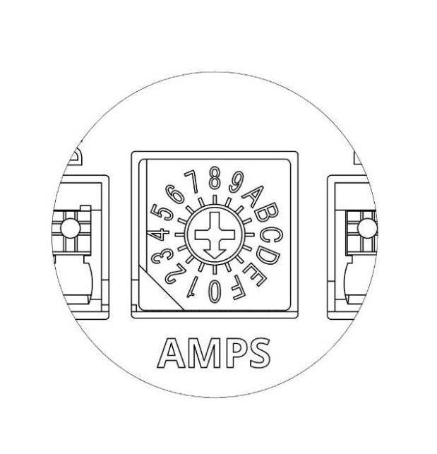
Use the AMPS rotary switch and the table below to configure the driver current according to your motor rated RMS current.
| Position | RMS current |
|---|---|
| 0 | 0.9 A |
| 1 | 1.0 A |
| 2 | 1.3 A |
| 3 | 1.6 A |
| 4 | 1.8 A |
| 5 | 2.0 A |
| 6 | 2.2 A |
| 7 | 2.4 A |
| 8 | 2.6 A |
| 9 | 3.0 A |
| A | 3.5 A |
| B | 4.0 A |
| C | 4.5 A |
| D | 5.0 A |
| E | 5.5 A |
| F | 6.0 A |
# μSTEP and STALL configuration switches
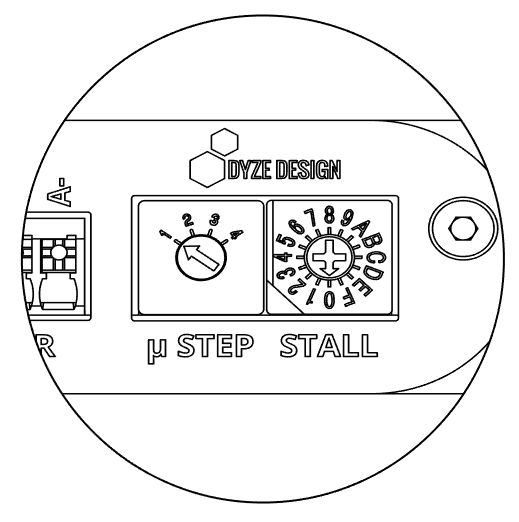
# μSTEP - microstep configuration
Microstep configurations are available on the μStep rotary switch. The main difference between interpolated and not interpolated motion lies in the smoothness and accuracy of movement. Interpolated motion produces more natural and precise trajectories, while non-interpolated motion can lead to rougher or less accurate paths. We recommend using the interpolated configuration
The preferred configuration is the second one, with a pulse/revolution ratio of 3200 (interpolated). This configuration will not only give you the smoothest displacement but also enhanced precision. Keep in mind that a pulse/revolution ratio of 6400 might be considered a little excessive.
| Position | 1 | 2 | 3 | 4 |
|---|---|---|---|---|
| Pulse/rev | 1600 interpolated | 3200 interpolated | 3200 not interpolated | 6400 not interpolated |
| Microstep | 8 | 16 | 16 | 32 |
# STALL - Stall detection configuration
Use the stall rotary switch to configure the driver stall detection threshold. Low sensitivity to high sensitivity (1 to F)
WARNING
The position 0 disables the stallguard™ and the coolstep™ features.
Enabling CoolStep is essential for optimizing power consumption, reducing motor noise, and achieving smooth motor displacement. Therefore, it's necessary to configure the stall switch even if you don't intend to use the StallGuard feature. Please refer to the “Stall switch configuration” section for more information."
| Position | Stallguard sensitivity |
|---|---|
| 0 | Stallguard and coolstep are disable |
| 1 | -7 (Low sensitivity) |
| 2 | -6 |
| 3 | -5 |
| 4 | -4 |
| 5 | -3 |
| 6 | -2 |
| 7 | -1 |
| 8 | 0 |
| 9 | +1 |
| A | +2 |
| B | +3 |
| C | +4 |
| D | +5 |
| E | +6 |
| F | +7 (High sensitivity) |
# Stallguard™
The Stallguard™ is a high precision sensorless motor load detection developed by Trinamic. It can be used as a motor stall detector or to replace an axle endstop switch.
# Coolstep™
The coolstep™ (developed by Trinamic) is a dynamic current control feature based on stallguard values, the coolstep reduces heat generation and optimizes the power consumption. This feature works better if the stall switch is properly configured. The coolstep is disabled when the stall switch is in position 0.
# Stall switch configuration
WARNING
Make sure to have properly configured the μStep and the amps switches before doing this procedure.
Follow the calibration instructions below.
- Put the stall switch in the F position (high sensibility).
- Run a long displacement sequence on the motor that you want to calibrate.
- While the motor is running, decrease the sensibility (stall switch) until the stall indicator turns off.
If your printer will run at 60 RPM or more and you want to use the stallguard feature. Follow the calibration instructions below.
Step 1: Coarse adjustment
- Put the stall switch in the F position (high sensibility)
- Run the motor in your system at 60 RPM (1 turn per second) or more.
- While the motor is running, decrease the sensitivity (stall switch) until the stall indicator turns off.
Step 2: Fine adjustment
- Run the motor in your system at 60 RPM (1 turn per second) or more.
- Execute some direction changes, check the stall indicator at the same time.
- If the stall indicator blinks, decrease the sensitivity (stall switch) a notch.
# Firmware configuration
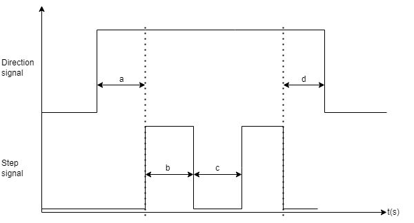
| Description | Minimum | Typical | |
|---|---|---|---|
| a | Direction setup time | 100ns | 1us |
| b | Step pulse width | 100ns | 1us |
| c | Step interval | 100ns | 1us |
| d | Step to direction hold time | 100ns | 1us |
# Marlin Firmware
# Modifications on the configuration.h file
# Motor enable
#define X_ENABLE_ON 0
#define Y_ENABLE_ON 0
#define Z_ENABLE_ON 0
#define E_ENABLE_ON 0 // For all extruders
These options set the pin states used for stepper enable. When you are using the Dyze Stepper you need to set this option to 0(Low), because the DyzeStepper will be active when the enable pin is low.
# Motor Disable
#define DISABLE_X false
#define DISABLE_Y false
#define DISABLE_Z false
These options are being used to disable the stepper between movement.This feature was implemented as a hack to run steppers at higher-than-normal current in an effort to produce more torque at the cost of increased the heat for drivers and steppers. We don’t recommend activating this feature because disabling steppers can’t hold the carriage stable and the coolstep feature of the DyzeStepper will give current on torque demand. So the motor Disable feature is not very useful when you are using the Dyze Stepper.
# Motor Direction
#define INVERT_X_DIR false
#define INVERT_Y_DIR true
#define INVERT_Z_DIR false

#define INVERT_E0_DIR false
#define INVERT_E1_DIR false
#define INVERT_E2_DIR false
#define INVERT_E3_DIR false
#define INVERT_E4_DIR false
These settings reverse the motor direction, so depending on how you have plugged the motor you will maybe have to activate this setting. We recommend doing a small manual displacement, before doing anything else with your printer, to figure out if the motor direction is right.
# Modifications on the configuration_adv.h file
# Minimum Stepper Delay
//#define MINIMUM_STEPPER_POST_DIR_DELAY 650
//#define MINIMUM_STEPPER_PRE_DIR_DELAY 650
The default settings will work just fine, if you are using 3.3V to 5V control signals (dir, step and enable pins), but if the signal from your controller is above 5V, you must assign 1000 (ns) to both of those parameters.
# Minimum Stepper Pulse
#define MINIMUM_STEPPER_PULSE 2 // (µs) The smallest stepper pulse allowed
This setting must be greater than 1 (us) to work great in any situation with 3.3V to 48V control signals (dir, step and enable pins).
# Maximal Stepper Rate
//#define MAXIMUM_STEPPER_RATE 250000
The default setting will work just fine with the dyzeStepper, which is 1 Mhz / (2 * MINIMUM_STEPPER_PULSE)
# RepRap Firmware
To connect the Dyze stepper with the Duet board, it's necessary to use the Duet expansion breakout board.
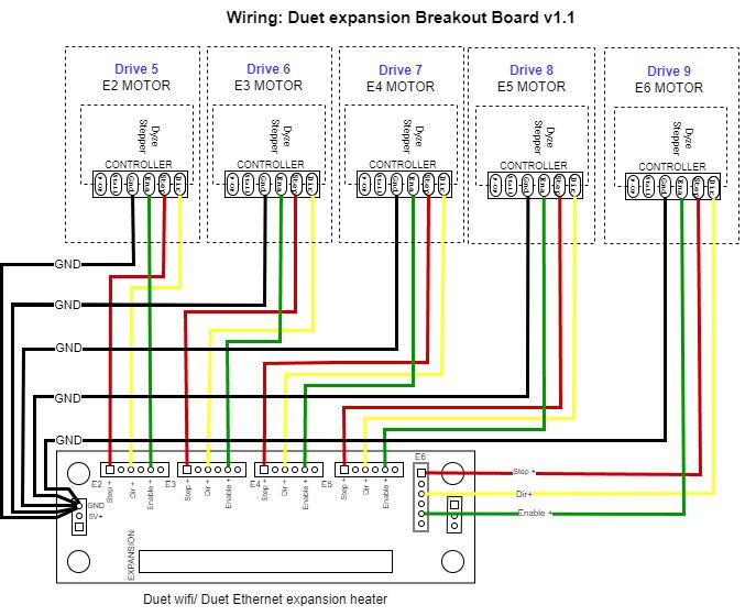
The expansion board provides differential output, whereas the Dyze stepper has isolated single-ended inputs. Please refer to the schematic above for guidance on how to connect the Dyze stepper to the expansion board.
WARNING
The ground should be split as closely as possible to the expansion board in order to create a star ground configuration.
In RepRap, the configuration is transferred to the controller through the config.g configuration file. Here's an example of a standard configuration for an extrusion system mapped to drive 8.
;;;;;;;;;;;;;;;;; DRIVE MAPPING ;;;;;;;;;;;;;;;;;;
M584 X- Y- Z- E8			  ; The pulsar drive is mapped to Drive 8, to customize
M350 X-- Y-- Z-- E16 I1 		; 16 Microstepping with interpolation enabled, to customize

;;;;;;;;;;;;;;;; DRIVE DIRECTION ;;;;;;;;;;;;;;;;;
M569 P8 S0 R1 			; Drive 8 goes backwards
# Drive mapping
M584 X- Y- Z- Ex ; The pulsar drive is mapped to Drive X
In the provided example, M584 assigns the appropriate axis to its corresponding drive number. Please refer to the wiring diagram above to determine the identifier (x) that corresponds to the drive you intend to configure.
# Microstepping
M350 X-- Y-- Z-- E16 I1 ; 16 Microstepping with interpolation enabled,
M350 configures the microstepping and interpolation status. In the following example, the extruder is configured with a microstepping value of 16 (E16), and interpolation (I1) is enabled. For most applications, we recommend setting the μStep switch to position 2.
| Position | 1 | 2 | 3 | 4 |
|---|---|---|---|---|
| Microstep | 8 (interpolated) | 16 (interpolated) | 16 (not interpolated) | 32 (not interpolated) |
# M569
M569 Px S1 R1 T2:2:2:2 ; Typhoon Extruder to Drive x, to customize from your own setup
M569 sets the rotation direction pin polarity, the enable pin polarity, the minimum step pulse, the minimum step interval, the direction setup time and step-to-direction hold time.
Px designates the drive being configured, specifically drive X.
S0 corresponds to backward movement, while S1 indicates forward movement. In this instance, The configuration of the direction pin depends on your printer's design and motor connection. We suggest performing slow manual movements to verify if the motor rotates in the intended direction.
R1 signifies the enable pin's polarity.
Tb:c:a:d represents values in microseconds for the minimum step pulse (b), minimum step interval (c), direction setup time (a), and step-to-direction hold time (d).
# Klipper Firmware
In Klipper, the stepper section ([stepper_x], [stepper_y], [stepper_z] or [extruder]) has to be modified in the printer.cfg file. Here's an example of how these sections should be configured:
[stepper_x]
step_pin: PF0
dir_pin: PF1
enable_pin: !PD7
microsteps: 16
# Define the pin on the controller
step_pin: xxx
dir_pin: yyy
enable_pin: !zzz ;Where xxx, yyy and zzz are the code names of those corresponding pins on your motherboard documentation for Klipper
The Dyze stepper's step pin operates in an active-high manner, so using an invert sign (!) shouldn't be necessary. The configuration of the direction pin relies on your printer's design and motor connection. We recommend performing slow manual movements to ascertain whether inversion of this pin is required. The enable pin for the Dyze stepper must always be inverted, as it is an active-low input. When no signal is present or when it is at logic low, the Dyze stepper will activate.
# Step pulse duration
step_pulse_duration: 0.000002
In Klipper the step pulse duration is by default at 2 us, you can keep it that way by not declaring this parameter or you can declare it, like the example above.
# Microsteps
microstep:16
Three microsteps options are possible with the Dyze Stepper depending on the position of the μStep switch:
| Position | 1 | 2 | 3 | 4 |
|---|---|---|---|---|
| Microstep | 8 (interpolated) | 16 (interpolated) | 16 (not interpolated) | 32 (not interpolated) |
We recommend using the μStep switch in position 2, for most applications.