# Zephyr™ 1.75mm Filament Extruder
- Revision
- Specifications
- General
- Safety Notice
- Critical Dos and Don'ts
- Use with Ø1.75 mm thermoplastic filament
- Use with proper product cooling
- Never drill any parts from the product
- Avoid prolonged idle periods
- Avoid collision with printed part by using vertical lift
- Prevent extended exposure to acidic materials, even during downtime
- Be cautious of excessive retraction
- Watch out for overcurrent on the motor
- Zephyr™ Pre-Print Checklist
- Unboxing and Initial Assembly
- Installation / Mounting
- Wiring
- 3D Printer Guideline
- Firmware
- Using the Zephyr™ extruder
- Final Preparations and Powering On
- Initial Verification Checks
- Ø1.75mm Thermoplastic Filament Insertion & Grip force adjustment
- Slicer and Print Settings
- Calibrating the flow
- Using retraction
- Benchmarked Performance
- Printing Speed
- Non Planar
- Grip Force Adjustment
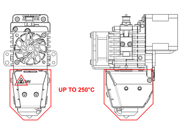
- High Temperature Use
- Compatible Dyze Design Products
- Maintenance & Troubleshooting
- Dehumidifying Maintenance Routine
# Revision
| Date | Revision | Modifications | Autor |
|---|---|---|---|
| 2024-06-27 | R001 | Initial Release | William Regnaud |
| 2025-05-14 | R002 | V4.0 update | William Regnaud |
| 2026-01-08 | R003 | V4.1 update | William Regnaud |
# Specifications
See product specification here. (opens new window)
# General
# What’s Included
| Item | Quantity |
|---|---|
| Zephyr™ high performance filament extruder | 1 |
| Mounting Hardware (M4X10 Low Profile cap screw) | 2 |
# Available accessories with your Zephyr™ Extruder
| Item | Quantity |
|---|---|
| Aurora™ Motion Controller Driver | 1 |
| Dyze Design Digital Stepper Motor Driver | 1 |
| Dyze Design RoboSync™ Hub - Robotic Arm Integration | 1 |
| Dyze Design PT100 Amplifier Boards Boards | 1 |
| PID Temperature Controller (NOVUS N1040) | 1 |
| Filament Monitors: Orthus™ or Sentinel™ | 1 |
| Part Cooling Kit - Axial Fan Assembly - Required Fasteners | 1 |
* If you need any of these items, contact sales.
# What’s required
- 24VDC Power Supply minimum 15A
- Required for the Zephyr™ cooling fan (0.2A)
- Required for the Zephyr™ heater (6.0A)
- Required for the Part Cooling Add-On (0.5A)
- 24-48VDC Power Supply
- Required to drive the stepper driver (2.0A)
- 1 x PT100 Amplifier circuits.
- Required for PT100 readings
- 1 x Motion Controller
- Aurora™ Motion Controler
- Or any open-source, firmware available, 3D Printer Controller Board:
- Duet3D
- BTT SKR
- BTT Octopus
- MKS
- SmoothieBoard
- Rambo
- CNC Type
- 4th axis
- Temperature control
- Robotic Arm
- Dyze Design RoboSync™ Hub (Robotic Arm Process Cabinet)
# Safety Notice
Heat Hazard
Allow product to cool completely before maintenance to prevent burns.
Electrical Hazard
Disconnect power before maintenance. Avoid contact with exposed wires.
Hazardous Emissions
Consult polymer safety data sheets. Implement appropriate containment and filtration if necessary.
Verify Mechanical Limits
Ensure the machine's limit switches and software limits are correctly configured. Proper configuration is critical to prevent mechanical collisions and to avoid excessive strain on cables during operation. Failure to do so may result in damage to the equipment.
Verify Thermal Protection
Confirm the firmware has active thermal protection enabled, including a maximum temperature limit for the extruder. This is essential to ensure the extruder does not exceed its specified safe operating temperature, which could otherwise lead to component damage or create a fire hazard.
# Critical Dos and Don'ts
# Use with Ø1.75 mm thermoplastic filament
Operate this equipment exclusively with Ø1.75 mm thermoplastic or fiber-reinforced thermoplastic filaments to ensure predictable performance and prevent damage. Using other material types may lead to unreliable results or equipment malfunction.
# Use with proper product cooling
Ensure adequate cooling of the cold zone to prevent overheating, which can cause product malfunctions and clogs. Insufficient cooling may necessitate disassembly for lengthy maintenance and clog removal.
# Never drill any parts from the product
Do not drill or attempt to modify any components of the product. Many parts are specifically hardened or possess critical surface finishes. Drilling can damage these components or cause the drill bit to break and become lodged within the unit.
# Avoid prolonged idle periods
Minimize extended idle times while the extruder is at operational temperature without active extrusion. Prolonged idling can lead to polymer degradation within the system, potentially causing clogs.
# Avoid collision with printed part by using vertical lift
Implement a vertical lift (Z-lift) strategy during travel moves to prevent collisions between the nozzle and the printed object. The minimum vertical lift should correspond to the layer thickness (e.g., a 1.00mm lift for 1.00mm layers). This practice is crucial for preventing equipment damage and ensuring print quality, especially as some slicer software may not fully optimize toolpaths for large-format printing, leading to potential over-extruded areas.
# Prevent extended exposure to acidic materials, even during downtime
To maintain equipment integrity and longevity, it is crucial to prevent extended exposure of the extruder components to acidic or corrosive materials, especially during periods of downtime. Ensure such materials are not left in the hotzone; always perform a thorough purge with a neutral cleaning material after processing them. Below is a non-exhaustive list of polymers and additives that require careful management due to their potential to release corrosive substances:
- PVC (Polyvinyl Chloride)
- Corrosive Byproduct: Upon heating, PVC can decompose and release hydrochloric acid (HCl), a substance highly corrosive to metal components, particularly steel.
- Accumulation Risk: Prolonged exposure or repeated processing without proper cleaning can lead to an accumulation of acidic residues, accelerating corrosion.
- Fluoropolymers (e.g., PTFE, FEP, PFA)
- Aggressive Acid Formation: The processing of fluoropolymers can result in the formation of hydrofluoric acid (HF). HF is extremely corrosive and can damage most metals and other common extruder components.
- Polymers with Acidic or Basic Degradation Potential
- Polyamide (Nylon): Nylons are hygroscopic and can absorb moisture. Under processing conditions, this moisture can contribute to the formation of acidic or basic byproducts, leading to corrosion.
- Polylactic Acid (PLA): Thermal degradation of PLA can yield lactic acid, which can be corrosive to metallic parts over time.
- Polyurethanes (PU): Certain polyurethane formulations may degrade into acidic or basic compounds, posing a corrosion risk.
- Additives and Fillers
- Flame Retardants: Many flame retardants, particularly halogenated compounds (containing chlorine or bromine), can release corrosive acidic gases (e.g., HCl, HBr) at elevated processing temperatures.
Adherence to these guidelines, including prompt and proper purging procedures, is essential for maximizing the operational lifespan and consistent performance of your extruder. Always consult material safety data sheets (MSDS) for specific handling and processing recommendations for any new or unfamiliar polymer.
# Be cautious of excessive retraction
Adhere strictly to the recommended retraction settings detailed in the "Using retraction" section of this guide. Excessive retraction distances can pull molten polymer too far into the heat break, leading to solidification in the cold zone and subsequent clogging.
# Watch out for overcurrent on the motor
Prevent overcurrent conditions for the extruder motor. Excessive current can cause the motor to overheat, which in turn raises the temperature of the cold zone. This can lead to operational malfunctions and filament clogs.
WARNING
Motors damaged by overcurrent are not covered under our warranty policy. Each product's motor is tested to ensure proper function before shipping.
# Zephyr™ Pre-Print Checklist
# Mechanical Installation
☐ Zephyr™ extruder is securely mounted to the motion system.
☐ Nozzle is installed correctly and torqued (Factory torque of 12N*m).
☐ All mounting hardware (brackets, fans, accessories) is installed and tightened.
# Electrical & Wiring
☐ All cables are connected and secured.
☐ The stepper driver is configured
☐ PT100 temperature sensor is properly reading
☐ An emergency stop (E-stop) system is installed/configured and functional
☐ All electrical components are rated and wired according to specifications.
☐ Heater circuit is protected with a fuse.
# Safety Verification
☐ Firmware thermal protection is enabled
☐ Minimum and maximum temperature limits defined.
☐ Overshoot protection configured.
☐ Cooling system is operational: Product fan rotates upon system power-up.
☐ Adequate heatsink ventilation ensured.
☐ Firmware limit switches and Z-offset are properly configured.
☐ Z-offset compensation for nozzle thermal expansion is applied.
# Heater & Temperature System
☐ PID tuning has been performed.
# Motion & Drive System
☐ Extruder motor rotates clockwise during forward extrusion command.
☐ Gearbox is lubricated.
# Final Verification
☐ Run a controlled test extrusion to validate flow.
☐ Confirm extrusion is clean, consistent, and within temperature range.
☐ Load and start a calibration print (e.g., single-wall cube or flow tower).
# Unboxing and Initial Assembly
# Intended Use
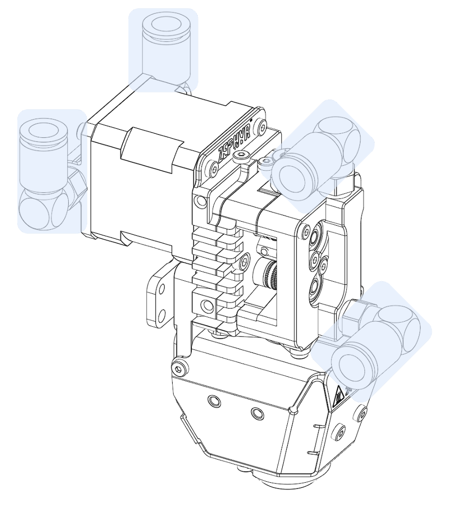
The Zephyr™ is an integrated extruder and hotend all-in-one solution engineered for professional additive manufacturing applications. Designed for compatibility with Ø1.75 mm thermoplastic filaments, this equipment is built to reliably process a wide range of thermoplastic materials and composites, delivering notable performance and stability. This solution offers a bridge between traditional desktop additive manufacturing and large scale industrial applications.
WARNING
Upon unboxing your Zephyr™ Extruder, a thorough inspection is critical. Should you discover any damage or identify any issues, please contact Dyze Design's support team immediately.
Dyze Design assumes no responsibility for the control and firmware of the Zephyr™, nor for its integration into 3D printers or robotic arms (collectively referred to as "motion systems").
The safe operation and control of the Zephyr™ depend on the motion system being equipped with appropriate, professionally compiled firmware that includes all necessary safety features. Additionally, a physical emergency stop button that disconnects power to the Zephyr™ is mandatory.
For safe maintenance, ensure the motion system is completely powered off and that both the Zephyr™ and the motion system have fully cooled down.
Maintenance procedures should only be performed by qualified personnel who are thoroughly familiar with this user manual.
Should you require assistance, do not hesitate to contact our support team.
Customized training and specialized support services are available upon request through our service plans. (Contact sales for more information)
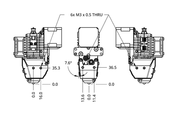
# Installation / Mounting
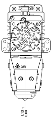
WARNING
Nozzle axis is 1.13 mm offset from the center of the machine
You can mount the Zephyr™ in several ways. The examples below show basic mounting methods. For the best extruder performance, carefully consider your gantry's specific design and any limitations when mounting.
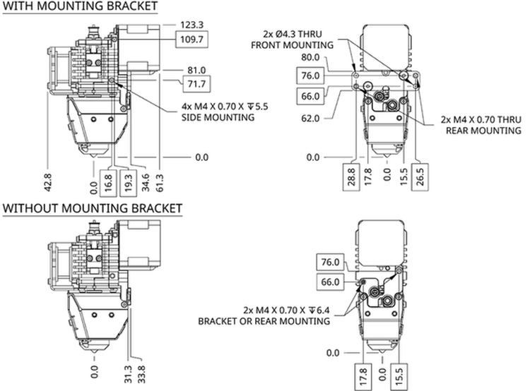
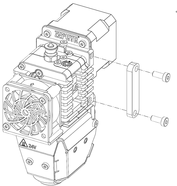
# Side Mounting (Either Side)
Remove mounting bracket.
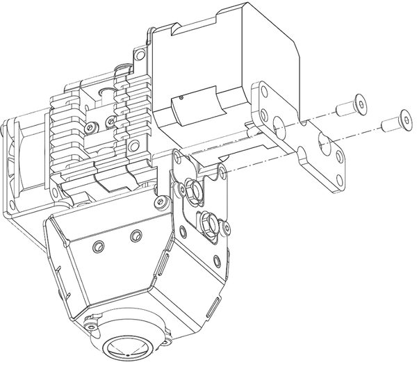
Use 2x M4 x 0.7 x 5.5 holes as anchoring points.
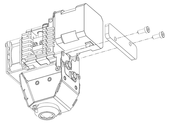
# Back Mounting without bracket
Remove mounting bracket
Use 2x M4 x 0.7 x 5.5 holes as anchoring points.
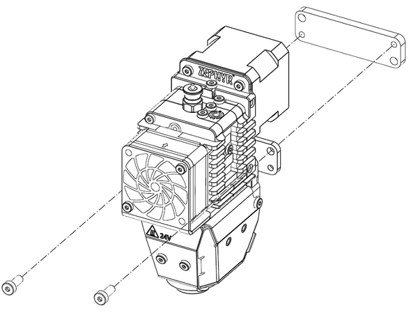
# Front Mounting with bracket
Use the 2x Ø4.3 clearance hole.
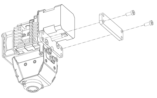
# Back Mounting with bracket
Use 2x M4 x 0.7 THRU holes as anchoring points
Check out our drawing page (opens new window) to get the 3D STEP file. Design your bracket according to the available mounting options.
# Water Cooling Add-On
The Zephyr™ comes with an air cooling system, engineered to operate effectively at ambient temperatures not exceeding 60°C. To enhance operating temperature, we offer the choice of incorporating a water cooling system allowing for sustained functionality at temperatures of up to 150°C. The two water loops are:
Motor Cooling Block (preinstalled on LC version)
Front Block (preinstalled on LC version)
Recommended Tubing : Ø6.35 mm (1/4") ID x Ø9.53mm (3/8") OD rated for push to connect (Durometer≈90A)
# Part Cooling & Bed leveling Add-On
The Zephyr™ is designed to offer you maximum flexibility:
Multiple Accessories Mounting Options: The Zephyr provides various ways to mount accessories on the hotzone.
Nozzle Shield: It includes a nozzle shield to insulate the cooling air lowering the nozzle’s temperature.
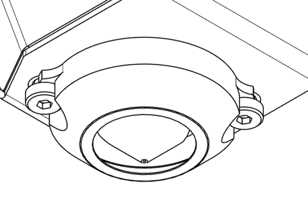
Customizable Solution : We offer a basic solution for part cooling. A compact blower fan fitted on a bracket on each side. However, we strongly recommend tailoring the part cooling system to your specific use case using the multiple mounting points readily available on the Zephyr's heat shield Use heat resistant materials for the parts in contact with the heat shield
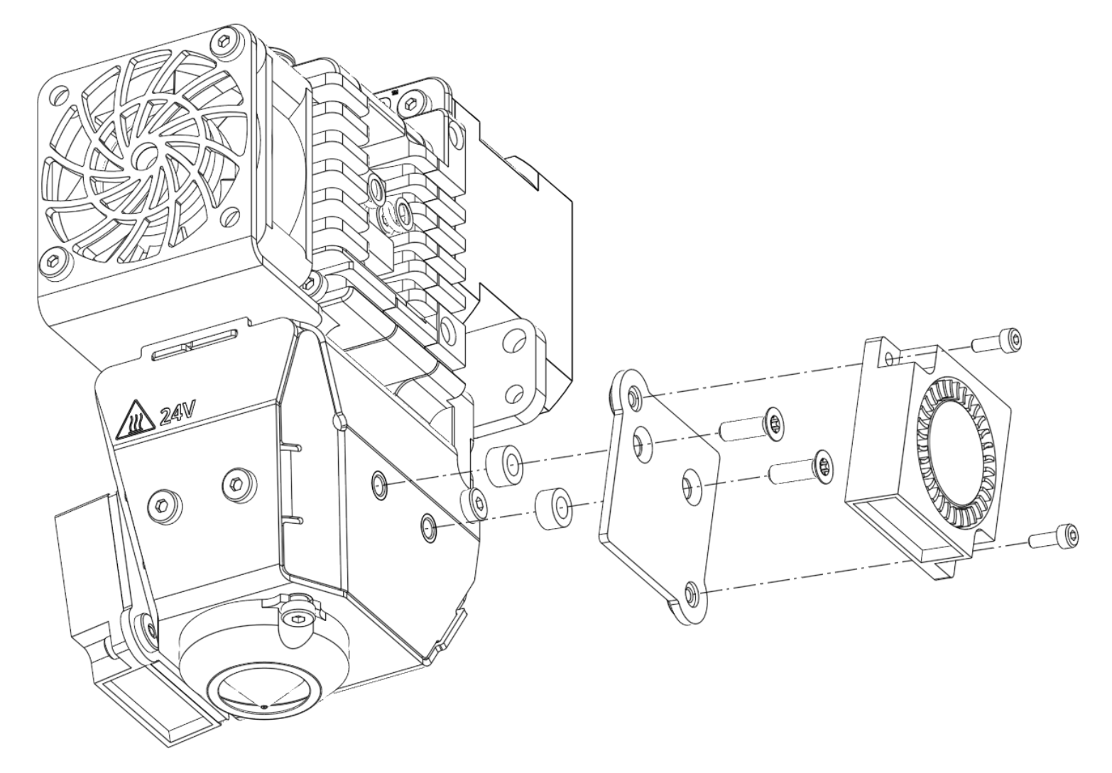
# 30 x 30 x 10 Blower Fan with 30cm bare ended wires
| Description | Value |
|---|---|
| Working ambient temperature | -10°C ~ 70°C |
| Rated Voltage | 12 VDC |
| Rated Current | 0.06A |
| Air Flow | 0.042 m3/min |
| Acoustical Noise | 29 dBA |
| Wires | 26 AWG |
| Wires | Polarity |
|---|---|
| Red | + |
| Black | - |
# Wiring
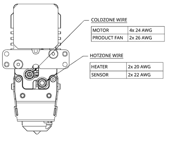
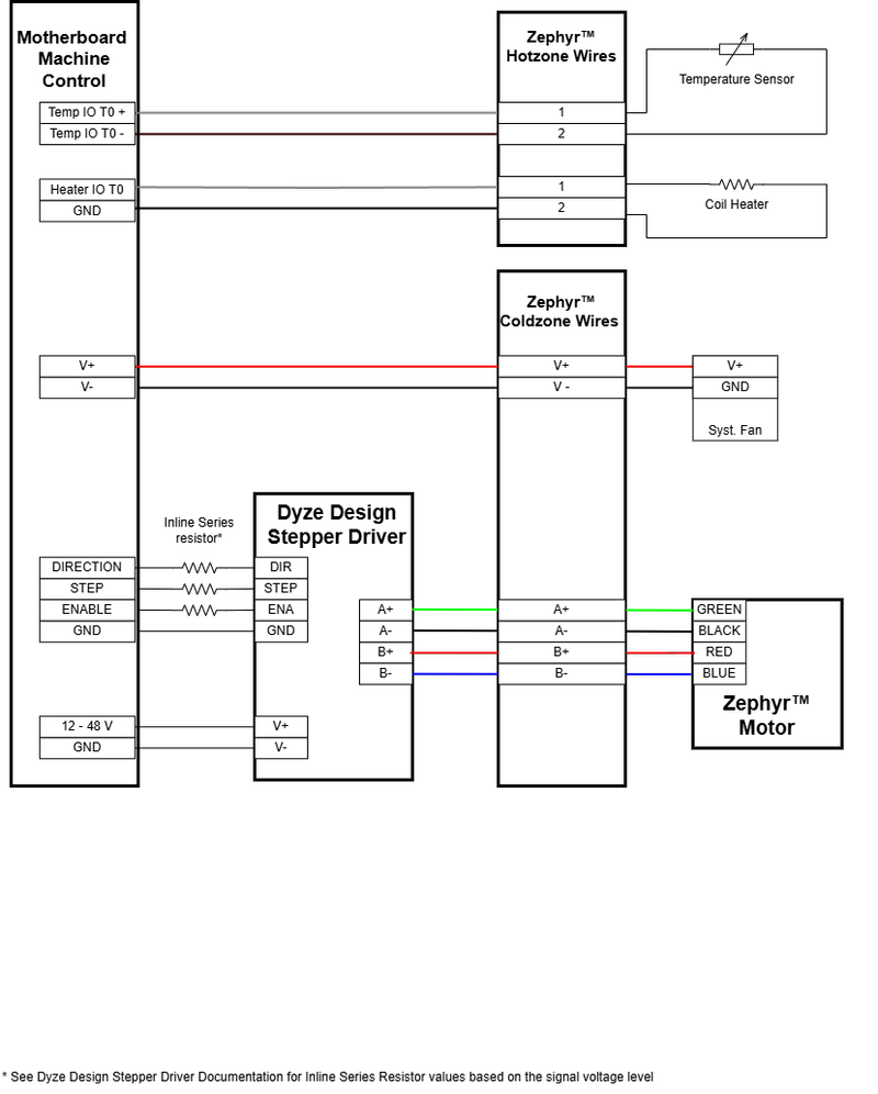
To ensure maximum flexibility, the Zephyr™ is supplied with two 25 cm cables: one designated for the 'coldzone' and the other for the 'hotzone'. Each cable contains several individual wires. These wires are identifiable and have bare ends, ready for connection. The cables have a temperature rating of up to 150°C. Consider the following options to connect the Zephyr™ to your gantry.
- Terminal blocks
- Wire to wire connectors
- Panel Mount connectors
- Tool boards
| Coldzone Wires | |
|---|---|
| Motor Wires 24 AWG 1.68 Amp | A+ : Green A- : Black B+ : Red B- : Blue |
| Product Fan Wires 26 AWG 0.12 Amp | V+ : Red V- : Black |
| Hotzone Wires | |
|---|---|
| Coil Heater 20 AWG 5.83 Amp | No polarity Kapton insulated wires Golden-Amber Color |
| PT100 Sensor 22 AWG | No Polarity Fiberglass insulated wires White Color |
# Emergency Stop (IMPORTANT SAFETY REQUIREMENT)
The Zephyr™ Extruder does not have a built-in emergency stop (E-stop) feature. For safe operation of the Extruder, you must implement an external emergency stop system.
This E-stop system is critical and must perform the following actions:
- Immediately cut all power to the Extruder’s heating elements.
- Immediately cut all power to the Extruder’s motor.
You can implement this essential safety feature in both ways:
- Through your 3D printer’s firmware and control interface.
- As a physical emergency stop circuit in your control cabinet.
# Temperature Sensors (PT100)
The Zephyr™ uses a PT100 sensor to monitor its temperature. To connect this sensor to your printer or robot's controller board, you will need a PT100 amplifier board. Since PT100 sensors are highly standardized, most commercially available PT100 amplifier boards are compatible. We also offer our ow Dyze PT100 amplifier board (opens new window), which you can find on our online store.
You will connect the PT100 amplifier board to an appropriate input pin on your 3D printer or robot controller. Common options for this connection include:
- Available pins or expansion pins (no pull-up): To find suitable expansion pins, please check your controller board's manual or pinout diagram. For more detailed instructions on setting up the amplifier board, please visit the PT100 the amplifier board documentation page (opens new window).
# Heater
Power Requirements and Control Signals
The Zephyr™ has a coil heater.
| Unit | Value |
|---|---|
| Voltage | 24V |
| Current | 5.83A |
| Power | 140W |
# Heaters Insulation
Heaters with coil heating elements can sometimes absorb moisture, particularly if they haven't been used for a while. This can lower the insulation resistance, potentially causing a small electrical current to leak to the ground. While this is often harmless, in some cases it can trip a GFCI (Ground Fault Circuit Interrupter) breaker.
To prevent this, especially when starting the heater for the first time or after a long period of disuse, you should perform a dehumidifying maintenance routine. This process, detailed below, will dry out the unit and restore proper insulation levels.
WARNING
You must run this procedure on the first startup. Skipping this step may damage the heater.
Dehumidifying Maintenance Routine
# Essential Power Components:
Fuse: For safety and overcurrent protection, we strongly recommend using a 6.5A fuse in the heater circuit.
Power MOSFET: A power MOSFET is required to safely control the high current needed by this heater.
- Check Your Controller: Some 3D printer or motion controller boards have built-in MOSFETs on their heater outputs. Verify if your controller’s heater output can handle the Zephyr™ heater's requirements.
- External MOSFET: If your controller cannot directly power the heater, or if its onboard MOSFET is not rated for this load, you must use an external power MOSFET module.
Controller Output Pins for Heater Control: You will need to connect the heater (usually through the power MOSFET) to a controllable output pin on your 3D printer or motion controller. Suitable pins on your controller can include:
Standard Heater/Extruder Output Pins (e.g., E0, E1, H0, H1):
- These are specifically designed for controlling heaters or fans.
- Ensure the output voltage matches the heater (24V).
- Crucially, confirm if this specific output on your controller can directly drive the required 5.83A of the heater or if it's a logic-level signal pin intended to control an external MOSFET (as discussed above).
Other Switched Output Pins (often on expansion headers):
- These are typically logic-level signal pins (e.g., outputting 3.3V or 5V PWM signals).
- If using these pins, they must be connected to an external power MOSFET module to control the 24V heater.
- Always consult your controller board’s manual or pinout diagram to identify and correctly configure these pins.
For detailed connection diagrams and instructions, please refer to the Zephyr™ Wiring Diagram.
# Stepper Driver
# Using your own stepper driver
You can choose to use your own stepper driver with the Zephyr™. If you do, it is essential to ensure that your chosen driver meets all of the Zephyr's™ motor specifications. Pay particular attention to the required current rating.
While some common stepper drivers may be compatible if they align with these specifications, please be aware of the following: We cannot provide full support for any issues that arise from using a stepper driver that is under-specified or does not meet the motor's requirements.
WARNING
Some stepper drivers and electronic boards use peak current for their current rating. Ensure you convert to the appropriate value.
| Description | Value |
|---|---|
| Drive Voltage | 24-48VDC |
| Motor Current (RMS) | 1.68A |
| Frame size | NEMA17 |
# Using Dyze Design's Stepper Driver
If you're using our Dyze Stepper Driver, you can refer to our Zephyr Quick Start Guide in our Dyze Stepper documentation.
# 3D Printer Guideline
# General
Printing without cooling is only possible with large parts. Thick and large layers take time to cool down, thus requiring you to reduce speed for small parts.
# Use Z lift
Raising the Z axis between each fast-travel is required. It will prevent any collision with the printed part. See the Slicer section for more info.
# Robotic Arm Guideline
If you plan on installing the Zephyr™ on a robotic Arm, you'll need to get some extra hardware to get the same features as a 3D printer controller. These items are the following:
- A robotic controller or PLC able to output STEP / DIR pulses for the stepper driver.
- A PT100 temperature sensor inputs (such as a Digital PID Temperature Controller).
info
Dyze Design is now offering an ethernet/ip controller to enable sync between your robot/robot controller and the Zephyr™ extruder (motor & flow control, heating elements, etc). Contact sales for more information.
# Firmware
# Marlin Firmware
2.0.x# Configuration.h
Set number of extruders:
#define EXTRUDERS 1
Set the correct temperature sensor values. Please refer to Marlin thermal settings (opens new window) to find the correct value based on your amplifier circuit or your actual setup.
#define TEMP_SENSOR_0 68 //could be 21
Set temperature min temp:
#define HEATER_0_MINTEMP 15
Set temperature max temp:
#define HEATER_0_MAXTEMP 475
Set the overshoot limit:
#define HOTEND_OVERSHOOT 15
WARNING
The heaters are very powerful, which is required for engineering and advanced polymers. If you are planning on printing low temperature, reduce the bang_max from 255 to 127.
Set custom power limits. Ranges from 0-255. 255 being 100% :
#define BANG_MAX 255
Increase the PID_functional_range:
#define PID_FUNCTIONAL_RANGE 40
Set the base PID values:
#define DEFAULT_Kp 7.48
#define DEFAULT_Ki 0.27
#define DEFAULT_Kd 52.63
Set the extruder steps per mm:
TIP
{X Axis, Y Axis, Z Axis, E Axis}
The value of the XYZ axis may vary and are shown as XXX.XX. The value of 389 serves as an initial reference point. Calibration will be necessary to optimize it for your specific configuration. You can find instructions for this calibration process in the "Calibrating the flow" section.
#define DEFAULT_AXIS_STEPS_PER_UNIT { XXX.XX, XXX.XX, XXX.XX, 389 }
Set the max feed rate:
TIP
{X Axis, Y Axis, Z Axis, E Axis}
The value of the XYZ axis may vary and are shown as XXX.XX
#define DEFAULT_MAX_FEEDRATE { XXX, XXX, XXX, 200 }
Switch enable logic for the extruder motor:
#define E_ENABLE_ON 1
# Configuration_adv.h
If you’re using a stepper driver carrier.
#define E0_DRIVER_TYPE name
If you’re using an external Stepper Driver, configure the external stepper driver
#define MINIMUM_STEPPER_POST_DIR_DELAY 500
#define MINIMUM_STEPPER_PRE_DIR_DELAY 500
#define MINIMUM_STEPPER_PULSE 3
#define MAXIMUM_STEPPER_RATE 200000
# PID tuning
Each heater needs to be tuned separately, use the M303 command in the console to run the tuning cycle as detailed here: https://marlinfw.org/docs/gcode/M303.html (opens new window)
Run the PID tuning without any material inside the MeltCore™ or only set a PID target temperature within your material range to avoid clogs.
Example:
M303 E0 S300 ;tune heater 0 with a target temperature of 300C
Once the tuning cycle is completed, save the new heater 0 values by entering the M500 command in the console (only works if EEPROM_SETTINGS is enabled in your firmware).
Repeat the process for the second heater. Example:
M303 E1 S300 ;tune heater 1 with a target temperature of 300C
Save the new values for heater 1 with the M500 command.
# RepRap Firmware
TIP
In your configuration file, you should find values similar to the ones below. However, we do recommend that you use the online ReRap Firmware configurator tool (opens new window).
WARNING
The following information is based on Duet 2 and RepRap Firmware 3.x. We strongly suggest that you also read the official Duet/RepRap documentation (opens new window) to make sure you correctly connected and configured your Duet board, PT100 (RTD) amplifier board and RepRap firmware version.
# Config.g
Set the correct temperature sensor values. Please refer to Duet documentation to find the correct value based on your amplifier circuit.
TIP
For the Duet 3 MB6HC, pins spi.cs1 should be replaced with spi.cs0.
M308 S1 P"spi.cs1" Y"rtd-max31865" ; configure sensor 1 as PT100 on pin e0temp
Set temperature max temp:
M143 H0 S475
Set the extruder steps per mm:
M92 XXXX.X YXXX.X ZXXX.X E389
TIP
The value of 389 serves as an initial reference point. Calibration will be necessary to optimize it for your specific configuration. You can find instructions for this calibration process in the "Calibrating the flow" section.
Set the max feed rate:
M203 XXXXX YXXXX ZXXXX E3000
Assign heater 1 to the zephyr "tool":
M563 P0 D0 H0 S"Zephyr"
Configure external stepper drivers (only if using the external stepper driver):
M569 PXXX SXXX R1 T2
# PID tuning
Run the PID tuning without any material inside the barrel or only set a PID target temperature within your material range to avoid clogs.
Using the M303 command in the Duet console, run the PID tuning for each heater as explained here: https://docs.duet3d.com/User_manual/Reference/Gcodes#m303-run-heater-tuning (opens new window).
Example:
M303 H0 S300 ;tune heater 1 with a target temperature of 300C
Once the tuning cycle is done for heater 0, copy the generated M307 command and replace them in your config.g file to the appropriate line.
If you encounter an overshooting error when trying to heat up the two heaters at the same time, try lowering the PWN value of the problematic heater even more.
Set maximum PWM (Change HX by H0, H1, H2, etc. based on your heater configuration):
M307 H0 S0.50 ;the S parameter will depend on your setup
# Repetier Firmware
TIP
In your configuration file, you should find values similar to the ones below. However, we do recommend that you use the online Repetier Firmware configurator tool (opens new window).
# Configuration.h
Set the correct temperature sensor values. Please refer to Repetier configurator tool (opens new window) to find the correct value based on your PT100 amplifier circuit.
#define EXT0_TEMPSENSOR_TYPE 13
Set temperature min temp:
#define MIN_DEFECT_TEMPERATURE 15
Set temperature max temp:
#define MAXTEMP 475
#define MAX_DEFECT_TEMPERATURE 500
WARNING
The heaters are very powerful, which is required for engineering and advanced polymers. If you are planning on printing low temperature, reduce the bang_max from 255 to 127.
Set maximum power output:
#define EXT0_PID_MAX 127
Set the extruder steps per mm:
#define EXT0_STEPS_PER_MM 389
TIP
The value of 389 serves as an initial reference point. Calibration will be necessary to optimize it for your specific configuration. You can find instructions for this calibration process in the "Calibrating the flow" section.
Set the max feed rate:
#define EXT0_MAX_FEEDRATE 200
Switch enable logic for the extruder motor:
#define EXT0_ENABLE_ON 1
# Configuration_adv.h
Configure the external stepper driver (if using the external stepper driver):
#define STEPPER_HIGH_DELAY 2
#define DIRECTION_DELAY 2
# PID tuning
Each heater needs to be tuned separately, use the M303 command in the console to run the tuning cycle as detailed here: https://github.com/repetier/Repetier-Firmware/blob/master/src/ArduinoAVR/Repetier/Repetier.ino#L191C3-L194C40 (opens new window)
Run the PID tuning without any material inside the barrel or only set a PID target temperature within your material range to avoid clogs.
Example for heater 0:
M303 P0 S300 X0 R4 C0 ;tune heater 0 with target temperature of 300C, saves result in EEPROM, 4 cycles, classic method
# Klipper Firmware
Open the printer.cfg file.
# Create your tool
Modify the [extruder] section as follows :
TIP
Replace the data in """___""" by your own
[extruder]
step_pin: """ the pin name where the stepper driver pullup + is plugged """
dir_pin: """ the pin name where the stepper driver direction + is plugged """
Enable_pin: """ the pin name where the stepper driver enable + is plugged """
# Check you board manufacturer documentation for these informations
microsteps: """ the microsteps settings your stepper driver is set at, ex: 16 """
rotation_distance: 8.226
# This is a starting average value that you will need to calibrate per material
full_steps_per_rotation: 200
gear_ratio: 3.09:1
#step_pulse_duration: 0.000002
# Uncomment the above line if you use the Dyze Stepper Driver
nozzle_diameter: """ your nozzle diameter in mm, ex: 1.2 """
filament_diameter: 1.75
heater_pin: """ the pin name where the bottom heater is plugged """
# Check you board manufacturer documentation for this information
sensor_type:  """ your amplifier board name, ex: PT100 INA826, custom pt100_5v or pt100_3v for Dyze PT100 Amplifier Board """
# See https://docs.dyzedesign.com/pt100-amplifier-board.html#klipper if you use our PT100 Amplifier
# See https://www.klipper3d.org/Config_Reference.html#common-temperature-amplifiers for list of compatibles temperature amplifier names
sensor_pin: """ the pin name where the PT100 for the bottom heater is plugged """
# Check you board manufacturer documentation for this information
control: pid
pid_kp = 7.48
pid_ki = 0.27
pid_kd = 52.63
# Starting values to be customized at first use with a PID autotuning routine
min_temp: 0
max_temp: 475
max_power: 1.0
# Try lowering this value if you have temperature overshooting issues
min_extrude_temp: 150
# Can be customized depending on your own material
# Calibrate the PID by running a PID autotune routine
Once you have set the heaters in printer.cfg, before using any material you need to run the PID autotuning procedure for each heater separately.
In the command console type and press enter:
PID_CALIBRATE HEATER=extruder TARGET=240
Once the test is completed and the tuning is done, type SAVE_CONFIG in the console to update the config file automatically with the new PID settings.
# Control the heaters temperature
In printer.cfg, create or modify your START_PRINT macro by adding the following:
[gcode_macro START_PRINT]
gcode:
  {% set BED_TEMP = params.BED_TEMP|default(60)|float %}
  {% set EXTRUDER_TEMP = params.EXTRUDER_TEMP|default(190)|float %}
  # Start bed heating
  M117 Heating Up...
  M140 S{BED_TEMP}
  # Start extruder heating
  M104 S{EXTRUDER_TEMP}
  # Set and wait for nozzle to reach temperature
  M117 Wait for Temp...
  # Wait for bed to reach temperature
  M190 S{BED_TEMP}
  M109 S{EXTRUDER_TEMP}
  M117 Printing...
Do the same for the END_PRINT macro:
[gcode_macro END_PRINT]
gcode:
  # Turn off bed, extruder, and fan
  M140 S0
  M104 S0
  M106 S0
In your slicer of choice, set your start g-code to this following line, keep it as a single continuous line for it to work:
PRINT_START BED_TEMP={bed_temperature} EXTRUDER_TEMP={extruder_temperature}
Set your end g-code to this:
END_PRINT
INFO
Replace {bed_temperature},{extruder_temperature} by your desired values.
Example:
START_PRINT BED_TEMP=80 EXTRUDER_TEMP=190
Example for Cura:
M140 S{material_bed_temperature_layer_0}
M104 S{material_print_temperature_layer_0}
START_PRINT BED_TEMP={material_bed_temperature_layer_0} EXTRUDER_TEMP={material_print_temperature_layer_0}

;The heater will use Cura print settings temperature

;M190 S{material_bed_temperature_layer_0}
;M109 S{material_print_temperature_layer_0}
;We use M140 and M104 dummy preheat lines that will be overriden just after
;This is to prevent certain versions of Cura from adding their own automatic ones
If you use Cura and possibly with other slicers you might have to open the gcode in a code editor and remove any automatically generated M104 and M109 commands that could interfere with your custom chosen temperatures.
# Using the Zephyr™ extruder
# Final Preparations and Powering On
Ensure the following steps are complete:
- The unit is securely mounted.
- The necessary software has been configured.
- All electrical connections are correctly and safely finished.
Once these preparations are done, the next step is to turn on the power to the unit.
# Initial Verification Checks
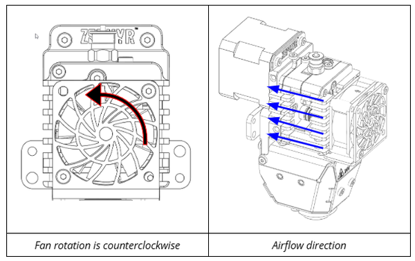
- Verify Cooling System Operation: Confirm that your cooling system is working correctly and effectively. In this case, the product fan must turn at all times when the additive manufacturing machine is powered on.
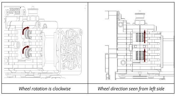
- Check Extrusion Motor Direction: Using your control interface, send a low-speed extrusion command to the unit.
Observe the extruder's drive wheels or gears. Confirm that they rotate clockwise (this is the typical direction to feed material into the extruder).
- Test Heater and Temperature Sensor: Set the heater to a low temperature (for example, between 50°C and 75°C).
Monitor the temperature reading from the corresponding sensor on your control interface.
Verify two things:
- The heater element itself starts to warm up. (Exercise caution if you attempt to feel warmth).
- The temperature reading from the sensor begins to increase towards your setpoint.
# Ø1.75mm Thermoplastic Filament Insertion & Grip force adjustment
The Zephyr™ Extruder is designed for use with Ø1.75mm thermoplastic filaments, including thermoplastic-based composite materials. It can effectively process both rigid and flexible types of thermoplastics.
WARNING
Important Note on Temperature: Always refer to the filament manufacturer's recommended temperature settings. Use these as your initial extrusion temperature.
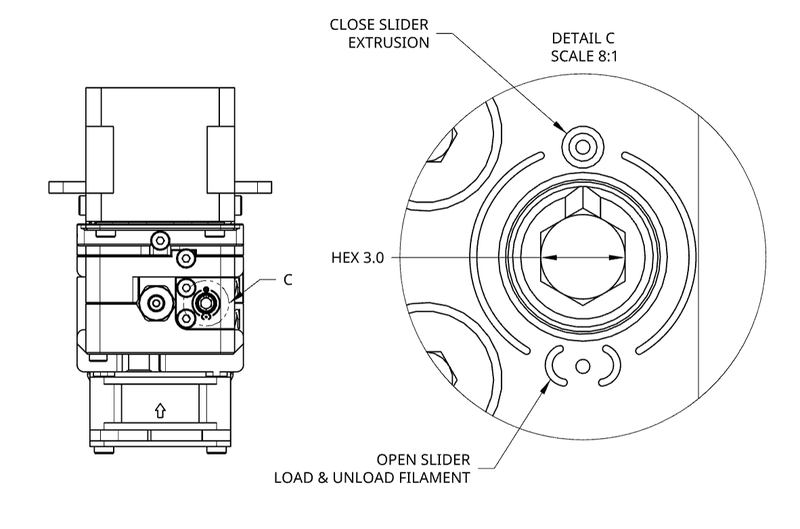
# Understanding the Filament Grip Cam
The extruder has a cam mechanism that controls the grip on the filament. You will need a 3mm Allen key or screwdriver to operate this cam.
- Open Position: Turn the cam so the notch aligns with the 'Open' mark. This releases the grip, allowing you to insert or remove filament.
- Closed Position: Turn the cam so the notch aligns with the 'Closed' mark. This engages the grip, holding the filament securely for printing.
# How to Load Filament
Heat Extruder: Set to the filament’s recommended operating temperature and wait for it to stabilize.
Open Filament Grip: Use a 3mm Allen key or screwdriver to turn the cam notch to the 'Open' position.
Insert Filament: Gently feed the Ø1.75mm filament into the extruder's pushfit until it reaches the hot nozzle and a small amount begins to extrude from the nozzle tip.
Close Filament Grip: Using the same tool, turn the cam notch back to the 'Closed' position to secure the filament.
# How to Unload Filament
Heat Extruder: Ensure it's at the filament’s recommended operating temperature (reheat if it has cooled).
Open Filament Grip: Use a 3mm Allen key or screwdriver to turn the cam notch to the 'Open' position.
Remove Filament: Gently but firmly, pull the filament straight out from the extruder's entry port.
Cool Down (Optional): If you're done printing or won't use the extruder for a while, turn off the heater or set it to a lower standby temperature.
# Slicer and Print Settings
# 1. Vertical Lift (Z-Hop)
To prevent the nozzle from hitting your print (especially over imperfections or curled edges), use your slicer's "vertical lift" or "Z-hop" setting. Set the lift distance to at least your layer height (e.g., for a 1.00mm layer, use ≥1.00mm Z-hop). This lifts the print head during travel, helping to avoid scrapes or collisions.
# 2. Nozzle Wipe Distance
Configure a nozzle wipe distance in your slicer, making it at least your line width (e.g., 3.50mm wipe for 3.50mm line width). This keeps the nozzle cleaner, reduces blobs/stringing, and improves print quality.
# 3. Line Width and Layer Height
The flat area on the nozzle tip is designed to shape the extruded plastic, helping to create a smooth and even surface on your prints.
Line Width Guidelines (relative to your Nozzle Orifice Diameter):
- General Range: For best results, your line width should typically be between 100% and 200% of your nozzle's orifice diameter.
- Avoid Too Wide: If your line width is much wider (e.g., significantly more than twice the nozzle orifice diameter), the nozzle's flat area may not effectively shape the plastic. This can lead to a poor surface finish and print defects like blobs.
- Avoid Too Narrow: Using a line width smaller than the nozzle orifice diameter is also not recommended, as it can result in poor print quality and weak layer adhesion.
Recommended Line Widths (based on Nozzle Orifice Diameter):
- For Standard Filaments: We strongly suggest a line width of approximately 1.5 times your nozzle orifice diameter.
- For Challenging Filaments (e.g., flexible materials, some composites): A line width between 1.1 and 1.25 times your nozzle orifice diameter usually works better. This approach can help reduce the pressure needed for extrusion and improve overall print results.
Settings Table for Line Width & Layer Height
Both layer height and line width settings directly depend on the nozzle orifice size you are using. The table below provides suggested minimum, maximum, and recommended settings for various nozzle sizes. Please consider these as starting points; experienced users may find that different settings work well for their specific needs and materials.
For more detailed information, please consult our comprehensive article (opens new window) on this topic
| Nozzle Size (mm) | Min Line Width (mm) | Max Line Width (mm) | Recommended Line Width (mm) | Min Layer Height (mm) | Max Layer Height (mm) | Recommended Layer Height (mm) |
|---|---|---|---|---|---|---|
| 0.40 | 0.24 | 0.80 | 0.60 | 0.10 | 0.32 | 0.20 |
| 0.60 | 0.36 | 1.20 | 0.90 | 0.15 | 0.48 | 0.30 |
| 0.90 | 0.54 | 1.80 | 1.35 | 0.23 | 0.72 | 0.45 |
| 1.20 | 0.72 | 2.40 | 1.80 | 0.30 | 0.96 | 0.60 |
| 1.80 | 1.08 | 3.96 | 2.70 | 0.45 | 1.44 | 0.90 |
# 4. Consider Nozzle Thermal Expansion During Bed Leveling
When you level your print bed while the nozzle is at room temperature (cold), it is crucial to remember that the nozzle assembly will expand when heated to its operating temperature. This thermal expansion causes the nozzle tip to become slightly lower relative to the bed.
- Example of Expansion: At an operating temperature of 200°C, the nozzle tip might be approximately 0.10mm lower than its position when it was cold.
- Why This Matters: If you do not account for this expansion when setting your Z-offset (especially during cold leveling), the nozzle can be too close to the bed once heated. This can lead to the nozzle scratching or damaging the print bed, or causing first layer adhesion problems and print failures.
- Action Required: Be cautious during Z homing and always compensate for this thermal expansion in your Z-offset.
Compensation for Cold Bed Leveling (Zephyr™ Heatcore): If you are leveling the bed when the Zephyr™ extruder is cold (e.g., at 20°C), use the table below to find the approximate additional Z-offset distance you need to apply to compensate for thermal expansion at your target printing temperature.
| Temperature (°C) | Extra length (mm) |
|---|---|
| 200 | 0.10 |
| 300 | 0.15 |
| 400 | 0.21 |
# Calibrating the flow
To get precise prints, your extruder's "steps/mm" setting must be calibrated. This ensures it pushes the correct amount of filament. Factors like temperature, material, and nozzle size can affect this.
# When to Calibrate Steps/mm:
- When first setting up your extruder.
- After making significant hardware changes to the extruder (e.g., changing gears). A common calibration method involves printing a test cube with a single-perimeter wall.
# Formula for Adjustment:
- Desired Wall Thickness: The target wall thickness set in your slicer (e.g., your line width for one wall).
- Actual Measured Wall Thickness: The average measured thickness of your printed single wall (use calipers for accuracy).
For example, if your Current Steps/mm is 404, Desired Wall Thickness is 1.5mm, and your Actual Measured Wall Thickness is 1.69mm (indicating over-extrusion):
Therefore, the new steps/mm should be set to approximately 358.6 for optimal calibration in this scenario.
Fine-Tuning and Adjusting for Different Materials:
- Iterate for Precision: For the best steps/mm accuracy with your main (or baseline) filament, you might need to print the test cube and recalculate 2-3 times.
- For Different Materials, Use Slicer Flow %: Once your steps/mm value is correctly set, do not change this machine setting for new types or brands of filament. Instead, use the "Flow Percentage" (also known as "Extrusion Multiplier") setting in your slicer software. This slicer setting allows you to easily fine-tune the extrusion amount for the specific characteristics of each different filament (like PLA, PETG, flexibles, different colors, etc.), ensuring good print quality across all materials.
# Using retraction
The Zephyr's™ short titanium heatbreak offers excellent thermal separation (preventing "heat creep") but needs very precise retraction settings to avoid clogs.
- Critical Retraction Limit: Your retraction distance must be less than 2.5mm.
- Reason: With this short heatbreak design, retracting filament 2.5mm or more can pull molten plastic into the cooler zone. There, the plastic can solidify, stick to the heatbreak walls, and cause a clog. Keeping retraction under 1mm ensures the filament's melted tip stays in the hot zone.
Using Retraction to Control Oozing To reduce oozing and blobs during non-printing moves, use carefully tuned retraction.
- Remember the Limit: Crucially, always keep your retraction distance less than the 2.5mm limit mentioned above.
- Fine-Tune: Find the minimum effective retraction distance and an appropriate speed within this strict sub-2.5mm range. This will help prevent both oozing and potential clogs.
- Flexible Material: Be careful with flexible material, retraction can damage the filament and prevent further extrusion.
| Min (backlash) | Max (Heatbreak length) | Recommended | |
|---|---|---|---|
| Retraction Distance (mm) | 0.5 | 2 | 1.25 |
| Retraction Speed (mm/s) | - | - | - |
| Z Lift | 1x Layer Height | 2x Layer Height | 1x Layer Height |
Retraction distance: Length of filament retracted. It varies depending on the type of material.
Retraction speed: Speed at which the extruder (opens new window) motor drives back the filament.
Z-axis elevation when retracted (Z lift): Helps clear any blob or bumps in the print while fast traveling
# Benchmarked Performance
# Flow rate @ Nozzle Size (mm³/s)
| Material | Brand | Max Temp (°C) | 0.4mm | 0.6mm | 0.9mm | 1.2mm | 1.8mm |
|---|---|---|---|---|---|---|---|
| PLA | Amz3D | 200 | 66 | 77 | |||
| PLA | Amz3D | 260 | 114 | 154 | |||
| PETG | Overture | 250 | 42 | 84 | |||
| PA12 - CF | Polymaker | 300 | 113 | ||||
| PEI | 3DxTech | 390 | 83 | ||||
| TPE | Ninjatek | 235 | 14 | ||||
| TPU | Sainsmart | 220 | 31 |
# Printing Speed
Refer to our 3D printer print speed calculation blog (opens new window) for more information.
For precise linear speed calculation, refer to our second section in our flow for pellets blog (opens new window).
Make sure you use the right speed for your nozzle size and layer thickness. You can refer to our product spec sheet for detailed output flow based on experimental data.
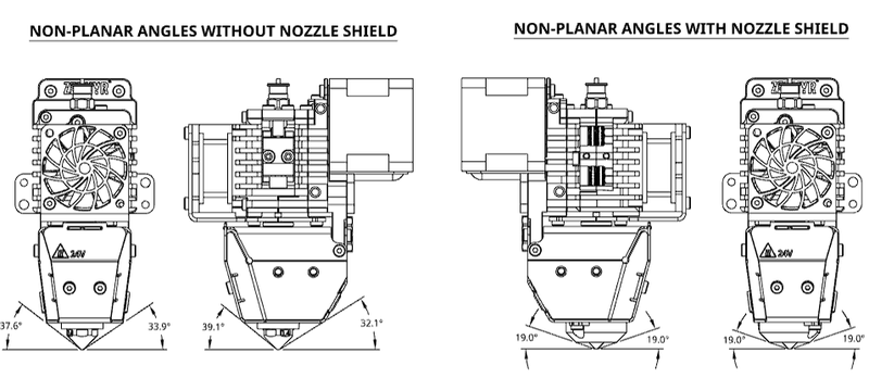
# Non Planar
Removing the Nozzle shield permits non-planar printing up to 32°. Doing so exposes the Nozzle to the environment. Using active part cooling will decrease maximum output flow and printing speed.
# Grip Force Adjustment
Using 2 shoulder screws on the right side, there’s the possibility to increase or lower the grip force applied by the extruder on the filament. Both screws need to be adjusted the same. The screw pitch is 0.5mm, meaning each complete turn moves the reference by 0.5mm. Measure the distance between the shoulder screw head and lower side of the slider and compare to the table below for grip force values. Failure to properly configure according to your application will result in inconsistent print. Gripping to hard will jam the filament beneath the lower extrusion wheel. Gripping to lightly will reduce stability and overall performance.
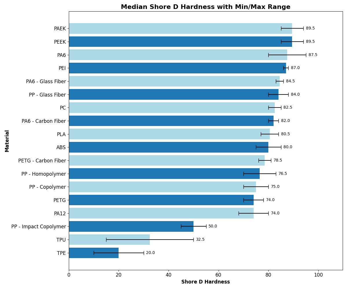
Increase the grip force on harder filament, decrease for softer or flexible filament. Below is a chart of common polymers and composite and their respective hardness. Refer to your manufacturer datasheet for specific hardness values.
- With the extruder empty (filament removed) set the cam to the Extrusion position
- Turn both screws clockwise to increase grip force. Turn counterclockwise to decrease grip force
- Make sure both screws are adjusted the same
- Open the grip mechanism, insert filament and close
- Run calibration routine
- Inspect your filament. Increase the grip force if there's no teeth indentation. Decrease the grip force if the filament is deformed into and oval
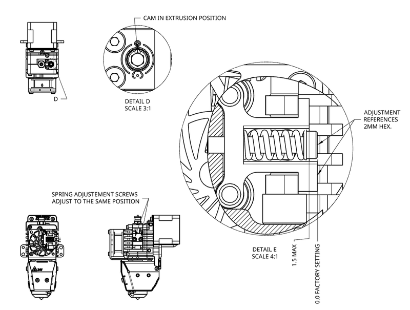
# M3 SHOULDER SCREWS ADJUSTEMENT (18 N per screw turn)
| SCREW TURNS - DISTANCE PER TURN 0.5MM | APPLIED LOAD ON FILAMENT (NEWTONS) | FILAMENT SHORE D HARDNESS |
|---|---|---|
| +3 / +1.5MM (MAX) | 158 | > 80 |
| +2 / +1.0MM | 142 | > 80 |
| +1 / 0.5MM | 130 | > 80 |
| 0 - FACTORY SETTING | 114 | 75 - 80 |
| -1 / -0.5MM | 100 | 70 - 75 |
| -2 / -1.0MM | 86 | 65 - 70 |
| -3 / -1.5MM | 72 | 60 - 65 |
| -4 / -2.0MM | 57 | 55 - 60 |
| -5 / -2.5MM | 42 | < 50 |
| -6 / -3.0MM | 29 | < 50 |
| -7 / -3.5MM | 14 | < 50 |
# High Temperature Use
The Zephyr™, along with its various add-ons, is designed to operate within an environmental temperature range of up to 60°C. Certain components have temperature limitations as follows: The product cooling fan and part cooling fans can both function effectively up to 60°C. Although you will lower the fan’s lifecycle above 40°C
If you intend to use this product in an environment with temperatures as high as 150°C, you should take the following factors into account:
- Implement the Water Cooling Add-on (will soon be available).
- Consider our Dyze Design’s Liquid Cooling System, should the need arise.
- Opt for High Temperature Liquid Cooling Tubing.
- Ensure that the cable harnesses & connectors are resistant to high temperatures.
- Do not use the Part Cooling Add-on in high-temperature environments.
We can assist you in acquiring any necessary upgrades or custom components required for high-temperature environments. If you need any of these items or questions, contact sales.
# Compatible Dyze Design Products
# Filament Sensor
To increase the reliability of your print. Consider adding the following products to your Zephyr™ Extruder.Contact sales for further information.
- Orthus™ (opens new window)is a smart and ultra-precise filament runout and jam sensor.
- Sentinel™ (opens new window)is a 3D printer filament detector and cleaner.
# PT100 amplifier
Coming with two PT100 sensors installed, the Zephyr™ provides accurate temperature readings on its working temperature range. Using the PT100 amplifier board (opens new window), you will reliably transmit those measurements to your controller.
# Stepper Driver
Using our Stepper Driver (opens new window) ensures your extruder will deliver the maximum of its capacity at all times.
# Nema17 Liquid Cooling Block
In an application where the environment is heated, consider using a Liquid Cooling block (opens new window) to ensure your motor stays in its temperature operating range. Works in tandem with the Liquid Cooled version of the Zephyr™ Extruder
# Maintenance & Troubleshooting
# Clogged Nozzle
# Causes
Clogging can be caused by a few factors. Make sure you understand which one is causing the issue and solve it before attempting a new print.
Bad slicer settings
- Too high retraction. Make sure you are not pulling the molten polymer too high. Refer to the retraction section
- Too high volumetric flow. Make sure you aren't asking too much of the Zephyr™. Thick and wide lines are misleading. Slow printing speed can still represent a high volumetric throughput.
Overheating the Heatbreak
- Malfunctioning system cooling. Inspect cooling system to find the problem
- Air
- Fan installed & running properly
- Heatsink exempt of dust and obstructions
- Air
- Coldzone overheating
- Environment temperature above rated specification
- Consider moving to liquid cooled version
- Lower environment temperature in enclosure
- Gearbox overheating
- Inspect bearings and gears
- Replace grease
- Motor overheating
- Verify stepper driver settings
- Install active motor cooling
- Environment temperature above rated specification
- Malfunctioning system cooling. Inspect cooling system to find the problem
# Unclogging techniques
Temporary extrude hotter
- Raise the temperature by steps of 10°C.
- Wait until the setpoint is reached.
- Send a slow extrusion command such as the one below.
G0 F60 E25- Repeat until the extruder is unclogged or the temperature is too high.
Hot Pull & Cold Pull
Follow the method explained here (opens new window)
Mechanical cleaning
- Unload filament
- Remove the nozzle assembly
- Apply heat
- Using a small tool with a >Ø1.5mm, remove the clog
# Coil Heater Moisture
If the extruder sat unused for a long period of time (many months), there’s a possibility that moisture has accumulated in the coil heater. It is noticeable as it will most likely trip breakers or blow fuses repeatedly. Follow those simple instructions to rectify or prevent the problem.
- Try heating for one hour at 75°C
- If the problem persists at this step, contact technical support
- Slowly increase the temperature in increments and let it sit for a short amount of time
- Keep the heater below water’s boiling point and let it sit ideally for up to 12 to 24 hours
- Heat at your desired thermoplastic process setpoint
- If the problem persists at this step, contact technical support
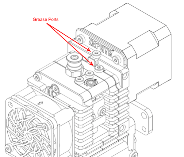
# Gears
To ensure proper product longevity and trouble-free operations, it is crucial for the gears to remain properly lubricated. You can access the grease holes from the top of the extruder. While turning the motor, apply Hasco FM Crystal Grease in the grease ports. It's worth noting that the Zephyr™ comes pre-greased with Hasco FM Crystal Grease . To simplify the application process, you may find it helpful to use a compact grease gun like the Astro Mini Grease Gun (opens new window).
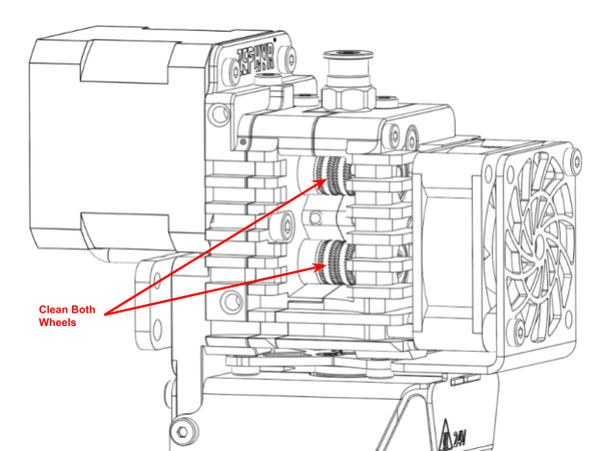
# Extrusion Wheels Cleaning
Using a Q-tip or a soft brush, clean the extrusion wheels when they are slowly turning. Removing most of the thermoplastic build-up. Once the plastic is dislodged from the teeth, blow compressed air on the wheels to remove the remaining bits.
# Periodic Inspection
To ensure the gearbox and its components last a long time, we recommend conducting periodic comprehensive inspections and maintenance. Regularly check all the gears and housing. To do this, disassemble the front end of the extruder. Use towels to clean away most of the old grease. Replace any gears that show excessive wear marks or have worn-down teeth.
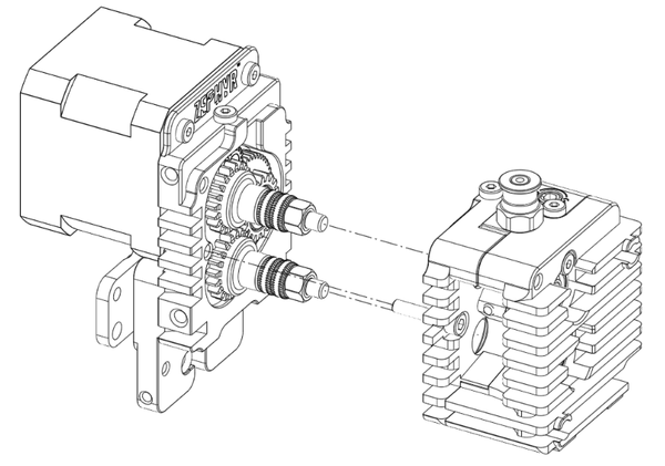
Follow the instructions below to remove the front end of the Zephyr™
Remove the filament and wait for cool down
Remove all covers
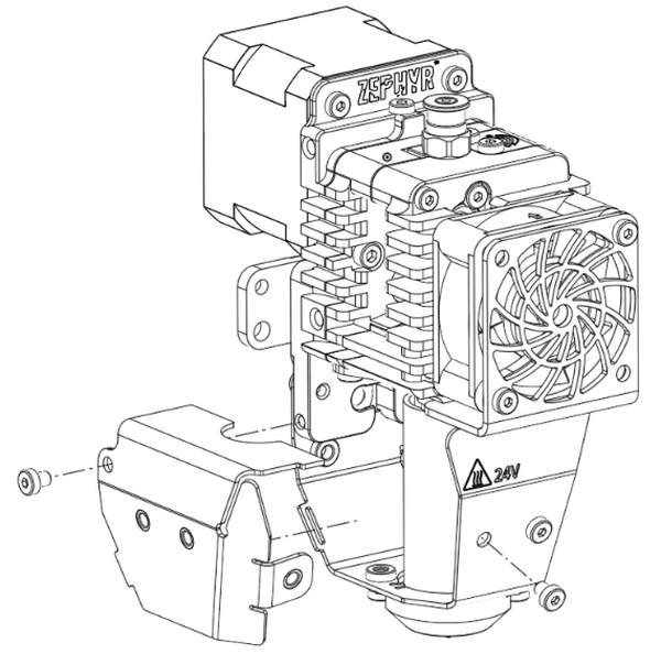
- Remove the hotend

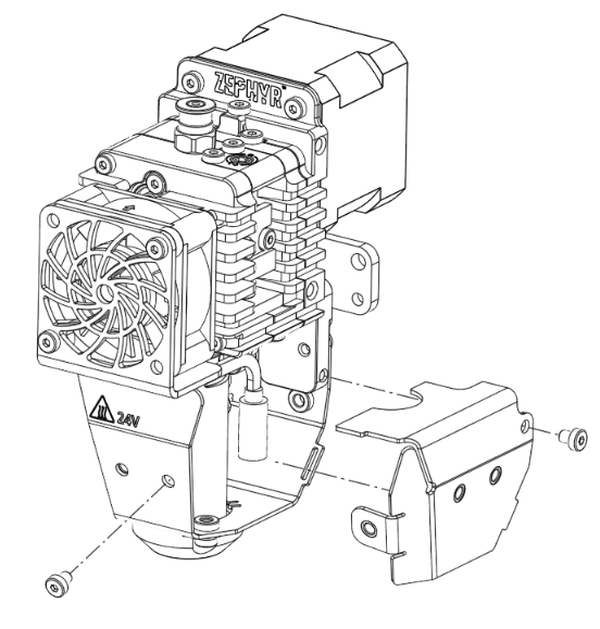
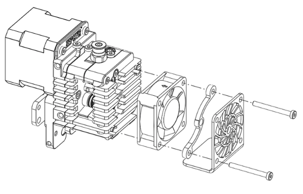
- Remove the System Cooling fan. Apply a maximum of 0.4 N*m on fan reassembly
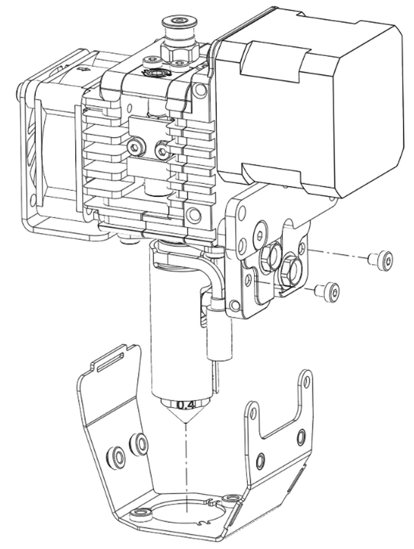
- Unscrew the 2 front screws on the Front block and loosen the screw maintaining the Gear block. Apply maximum 1 N*m on block reassembly
- Make sure the cam is in the opened position and remove the Front block and Gear block all together.
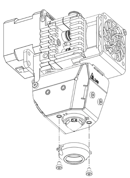
# Nozzle Change
The nozzle of the Zephyr™ can be easily removed when needed. To achieve this, please follow these steps using :
- 13 mm socket wrench
To do so you need to:
- Heat the product to the extrusion temperature
- Unload the filament
- Remove the part cooling bracket if there’s one
- Remove the Nozzle Shield Cover
- Unscrew the nozzle & Pull it out
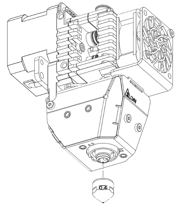
Replace the nozzle with a new one.
Screw it in place until it comes in contact with its seat. DO NOT OVERTIGHTEN Maximum 12 Nm
Re-install the part cooling bracket and Nozzle Shield Cover if needed
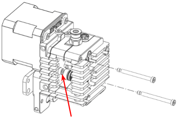
# Extrusion Wheel Maintenance
The extrusion wheels of the Zephyr are subject to wear over time as a result of normal operational use. Such wear may lead to inconsistencies in extrusion or cause the filament to slip during feeding. To extend the operational life of each wheel, they are manufactured with two functional surfaces. Should one surface become worn, the wheel can be flipped to engage the unused surface. Replacement of the wheels is required when both surfaces are worn.
To access, flip, or replace the extrusion wheels, please adhere to the following procedure:
- Follow the exact steps in the Periodic Inspection section to access the extrusion wheels.
- Remove the extrusion wheels.
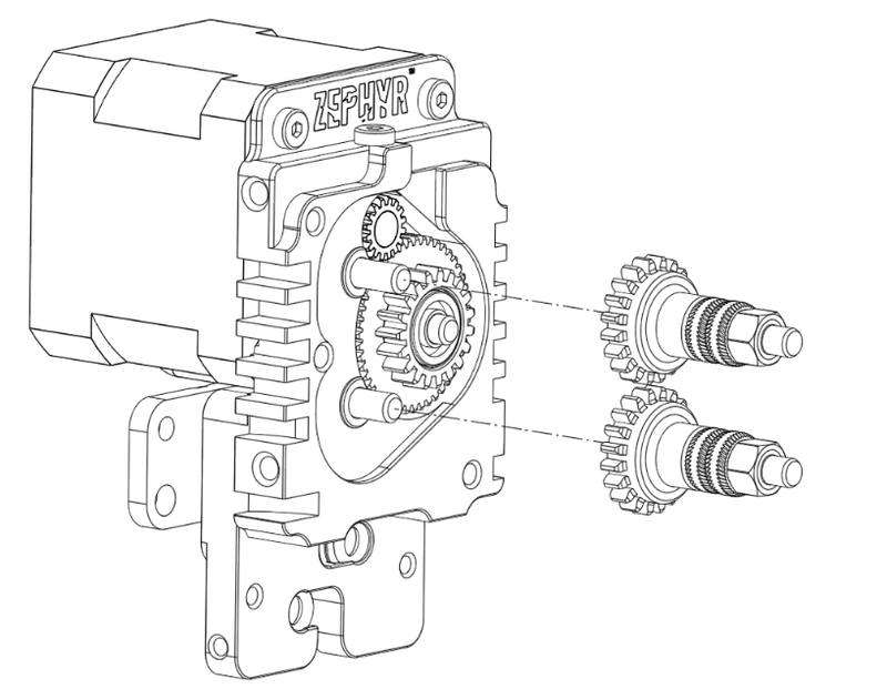
- Remove the nut holding the wheels on the driven shaft.
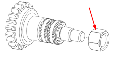
- Extrusion wheels can be either inverted or replaced with a new set. The teeth design is non-directional; therefore, clocking to a specific orientation is not required.
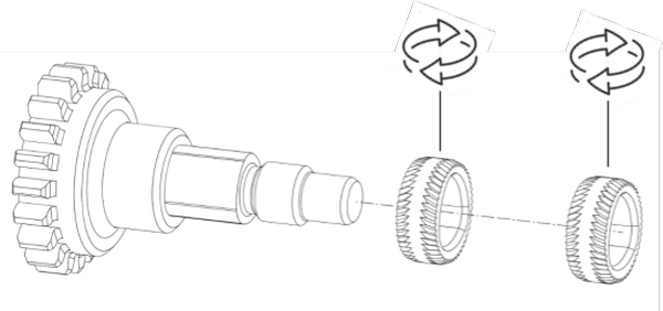
Reinstall the wheel-retaining nut to a torque of 7 Nm.
Reinstall the front end of the extruder
# Dehumidifying Maintenance Routine
Diagnosing the Problem
To diagnose the insulation, use a multimeter set to 200MΩ. Measure the resistance between one of the heater's power cables and the ground. A healthy reading should be above 1MΩ or show an "Open Circuit" reading.
If you get a low resistance reading, it's most likely due to moisture. This is a common issue that you can resolve by gently drying the heater.operating temperature.
The Drying Process
Follow these steps to safely remove moisture from the heater:
Turn on the printer and set the hot end temperature to 50-75°C. The goal is a gentle, sustained warmth. Maintain this temperature for at least 2 hours to allow the moisture time to fully evaporate.
Next, increase the hot end temperature to 95°C and hold it there for at least 2 more hours.
Use your multimeter to check the resistance again. When the multimeter shows an "open circuit" or "OL" reading, the heater is dry.
Once the heater is dry, you can safely run it at its normal operating temperature.