# Typhoon™ LCX & Typhoon™ Air 2.85mm Filament Extruder
# Revision
| Date | Revision | Modifications |
|---|---|---|
| 2023-09-29 | R001 | Initial Release |
| 2026-06-12 | R002 | Added details regarding PWM frequency in heaters |
# Specifications
See product specification here. (opens new window)
# General
# What’s Included
# Typhoon™ LCX
| Item | Quantity |
|---|---|
| Typhoon™ LCX 2.85mm Filament Extrusion Body | 1 |
| Typhoon™ Heatcore Pro (Standard or Non-Planar Configuration) | 1 |
| Liquid Cooling Fitting Kit (2* M8 x 1.00 Elbow or Compression Fitting and 2* M8 x 1.00 Plug) | 1 |
| Mounting Hardware (4* M4 x 10 Button head cap screw and 2* 4 x 10 Dowel pin) | 1 |
# Typhoon™ Air
| Typhoon™ Air 2.85mm Filament Extrusion Body | 1 |
|---|---|
| Typhoon™ Heatcore Pro (Standard or Non-Planar Configuration) | 1 |
| Fan Cable (2m) | 1 |
| Mounting Hardware (4* M4 x 10 Button head cap screw and 2* 4 x 16 Dowel pin | 1 |
# Available accessories with your Typhoon™ Extruder
| Item | Quantity |
|---|---|
| 25A 660VAC Solid State Relay (SSR) | 2 |
| Stepper Driver: Dyze Design’s Digital Stepper Motor Driver or Ethernet/IP Stepper Driver (STF06)) | 1 |
| Cable Harness for Heater & Signal (2m or 5m) | 1 |
| Motor cable (2m or 5m) | 1 |
| Dyze Design’s PT100 Amplifier Boards | 2 |
| Duet PT100 Daughter Boards | 1 |
| Dyze Design’s Liquid Cooling System | 1 |
* If you need any of these items, contact sales.
# What’s required
- 24VDC Power Supply
- Required for the Typhoon™ Air cooling fan
- Required for the Typhoon™ LCX (if using Dyze Design liquid cooling)
- 24-50VDC Power Supply
- For driving the stepper driver
- AC supply 50 or 60 Hz required for the heating elements totaling 400W
| Heater Nominal Tension (V) | Lower range (V) | Higher range (V) |
|---|---|---|
| 110V Heatcore | 100 | 130 |
| 220V Heatcore | 200 | 240 |
Note : Power is sized based on nominal tension value. Power will be reduced or increased depending on supplied voltage according to Ohm’s Law
- 2 x PT100 Amplifier circuits.
- Dyze Design amplifier
- RTD Amplifier for Duet & RepRapFirmware
- Any other equivalent
- Any open-source, firmware available, 3D Printer Controller Board
- Open Source types:
- Duet3D
- BTT SKR
- BTT Octopus
- MKS
- SmoothieBoard
- Rambo
- CNC Type
- 4th axis
- Temperature control
- Robotic Arm
- Dyze Design Robotic Arm Controller
- Open Source types:
# Additional requirements for Typhoon™ LCX
- Liquid Cooling System
- Dyze Design can offer a custom liquid cooling system tailored for 3D printing as an add-on with your extrusion system
WARNING
The Typhoon™ was designed to be actively cooled by a water loop. If you try to use it without a liquid cooling loop, you will experience issues.
# Unboxing and Initial Assembly
# Intended Use
The Typhoon™ Extruder has been designed for the purpose of extruding and melting thermoplastics and thermoplastic matrix composites within an additive manufacturing machine. Using filament of a diameter of 2.85 mm. Competent personnel with appropriate training are essential for the operation and maintenance of the Typhoon™ Extruder.
WARNING
It is of critical importance that you carry out an inspection upon unboxing your Typhoon™ Extruder. In the unlikely event that there’s damage or any issue. Get in touch with Dyze Design’s support team.
Dyze Design is not responsible for the Typhoon's control, integration to the 3D printer or robotic arm (summarized as motion system) and firmware. Safe control and operation of the Typhoon requires the motion system to have a proper firmware with enabled safety features compiled by qualified personnel as well as a physical emergency button which cuts power to the Typhoon. Safe maintenance requires the Motion System to be powered off and for the Typhoon and the motion system to have cooled down. Safe maintenance is to be done by qualified personnel familiar with this user manual.
Contact our support team if you require assistance.
Training and specialized support could also be offered on demand as part of our service plans. (Contact sales for more information)
# How to assemble your extruder
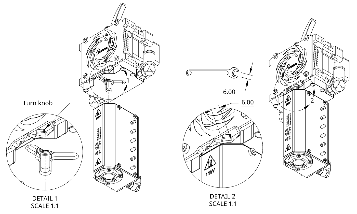
Your extruder arrives in 2 sub-assemblies. This assembly step can also be performed once the Typhoon™ Extruder Body is mounted on the carriage of your additive manufacturing machine.
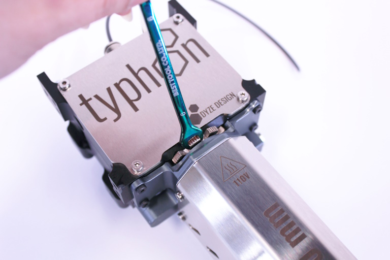
- Hand tighten the Heatcore into the Extruder until both faces are in contact
- Secure the heatcore using a 6 mm wrench. Turning 2-3 mm is enough.
# Installation / Mounting
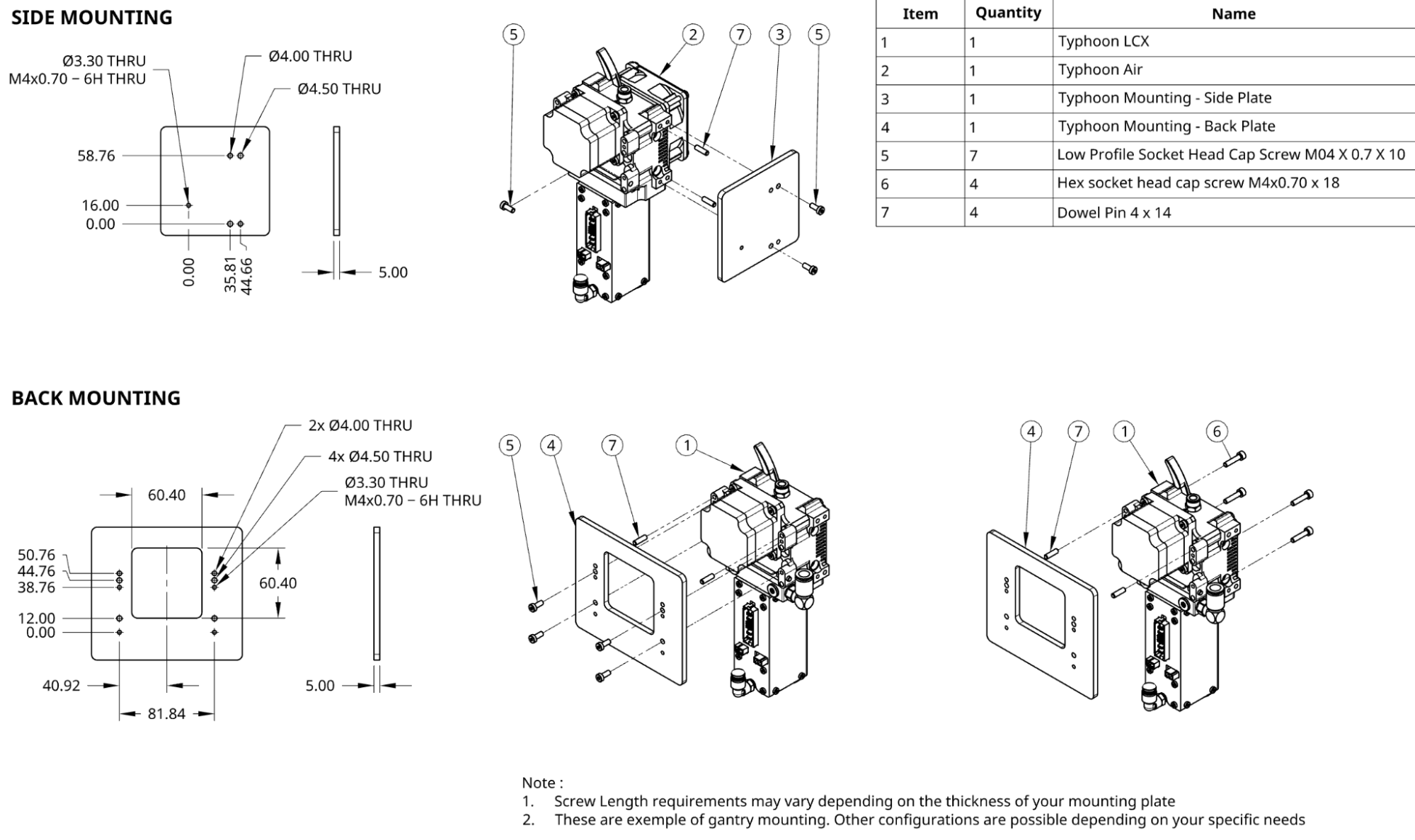
Mounting the Typhoon can be done from 3 faces; Left, Right, and Back. Each one have two possible ways for the screws; either through holes or tapped holes. Depending on your mounting plate, one solution might be easier to access. Each face has two dowels holes for accurate positioning.
- Threaded holes are M4x0.70 and thread engagement should be 7.00mm.
- Dowels Pins holes are 4.00mm x 6.00mm depth. 4 mm protrudes when using supplied dowel pins
Check out our drawing page to get the 3D STEP file. Design your bracket according to the available mounting options.
On the CAD file, consider the following references:
- 3.30mm holes are M4.00 x 0.70 threaded holes
- 4.00mm holes are reamed holes for dowels pins
- 4.50mm holes are clearance for M4 screws
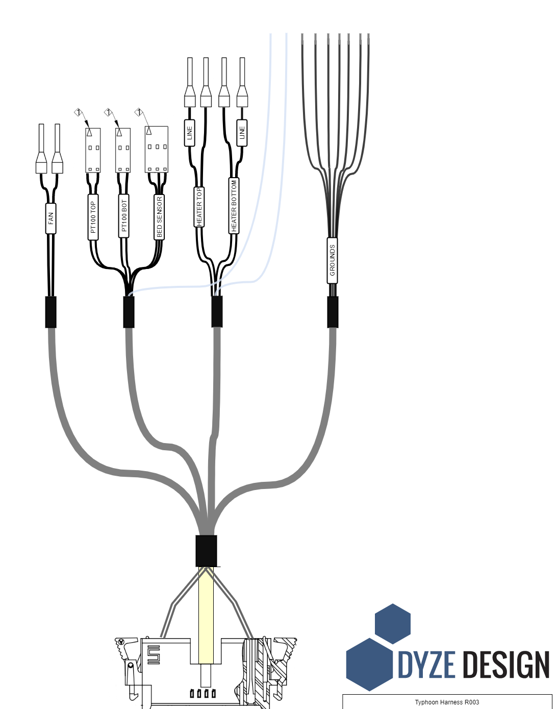
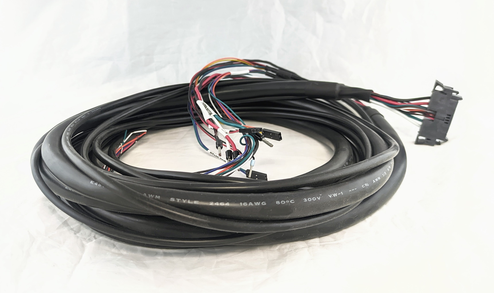
# Wiring
The Typhoon comes with a cable harness that is designed to connect from the Heatcore up to your electric box. The standard length is 2 meters, 5 meters is available upon request. A diagram is shown below with more information about the electrical connections.
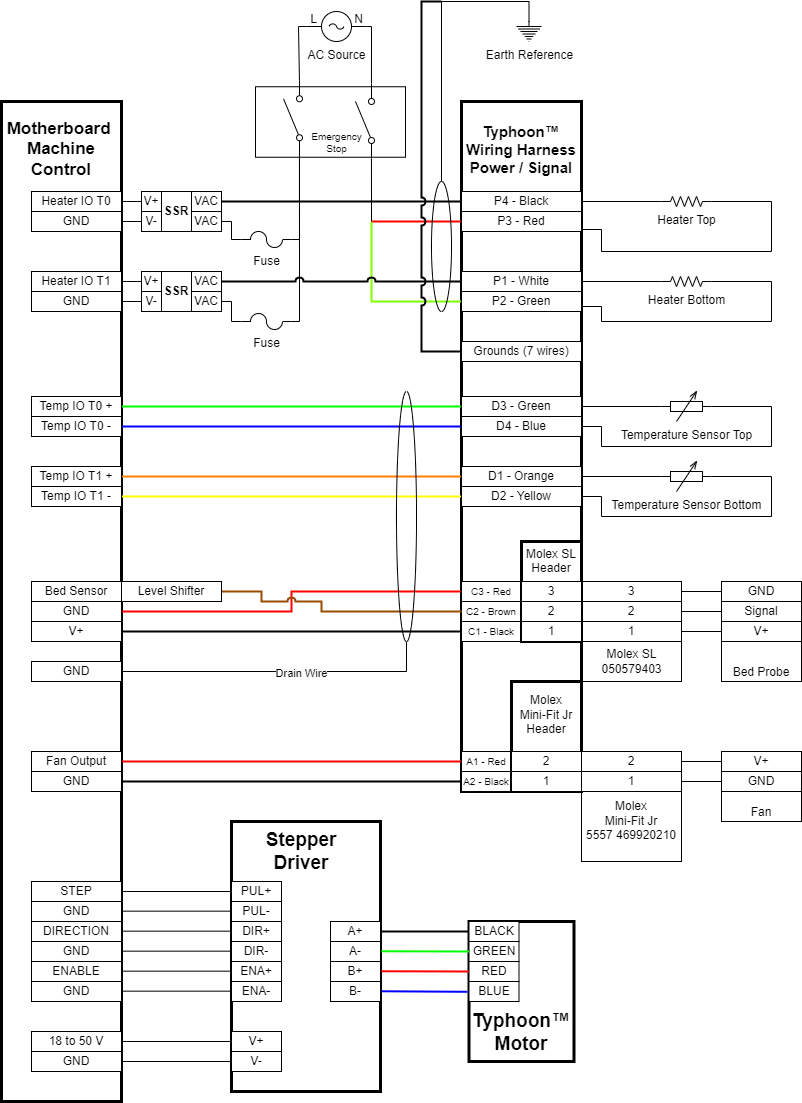
# Emergency Stop
The Typhoon Extruder does not have an emergency stop feature. An emergency stop loop is a must to operate the Extruder safely. The emergency stop must cut the power to the heating elements and the power supply of the motor. This feature can be implemented in your 3d printer firmware and control interface or physically in your control cabinet.
# Heaters
Each heater has its own SSR. Two SSR can be provided with the Typhoon.
WARNING
Note on SSR Selection and Configuration The SSRs provided are zero-crossing types, which are ideal for reducing electrical noise but require specific timing configurations. Depending on your chosen firmware (such as Klipper, Marlin, or RepRapFirmware), you must configure the PWM frequency for these heater outputs to a low rate, typically around 2 to 3 Hz. Setting the frequency too high will prevent a zero-crossing SSR from switching correctly, leading to unstable temperature control or a complete failure to heat.
The fuse is optional but strongly suggested. Each fuse should be rated according to the power rating:
- Top heater, 250 Watts, 2.5A for 120VAC and 1.25A for 240VAC systems
- Bottom heater, 150 Watts, 1.5A for 120VAC and 0.75A for 240VAC systems
Many pins can be used as the temperature output control. Your 3D Printer Controller (or motion controller) pins can be as below:
- The standard extruder output (E0, E1, E2, etc). These are usually rated at the same voltage as your main power supply (12VDC or 24VDC).
- Any available expansion pins. These can be determined by checking the 3D Printer Controller specification pins.
Please refer to the above diagram for wiring the Typhoon.
# Heaters Insulation
Heaters with coil heating elements can sometimes absorb moisture, particularly if they haven't been used for a while. This can lower the insulation resistance, potentially causing a small electrical current to leak to the ground. While this is often harmless, in some cases it can trip a GFCI (Ground Fault Circuit Interrupter) breaker.
To prevent this, especially when starting the heater for the first time or after a long period of disuse, you should perform a dehumidifying maintenance routine. This process, detailed below, will dry out the unit and restore proper insulation levels.
WARNING
You must run this procedure on the first startup. Skipping this step may damage the heater.
Dehumidifying Maintenance Routine
# Backplate Add-On Connectors
The Typhoon has two extra connectors at its back. One is for fans, the other is for the Z probe (bed sensor).
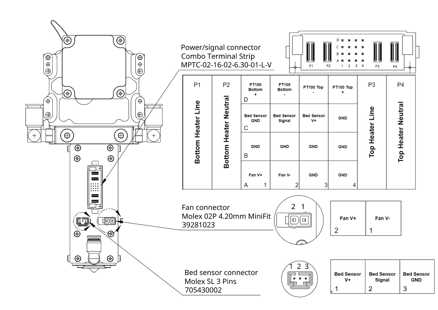
# Power / Signal connector
The Power / Signal connector mates with a Samtec 5.00 mm PowerStrip™
Mating Part Number : IMSC5-02-16-02-L
| Mating Housing | Mating Contact |
|---|---|
| Power (P1 - P4) | CC46L-1416-01-L |
| Signal (A1 - D4) | CC81L-2426-01-L |
# Fan connector
The fan connector mates with a Molex Mini-Fit Jr. Mating Part Number : 469920210
| Mating Housing | Mating Contact |
|---|---|
| Power | 457501111 |
| Pin 1 | Pin 2 |
|---|---|
| GND | V+ |
# Sensor connector
The sensor connector mates with a Molex SL. Mating Part Number : 50579403.
| Mating Housing | Mating Contact |
|---|---|
| Signal | 0016021124 |
| Pin 1 | Pin 2 | Pin 3 |
|---|---|---|
| V+ | Signal | GND |
# Typhoon™ Air Cooling Fan connector
The cooling fan connector mates with a Molex SL.
Mating Part Number : 0705410001
| Mating Housing | Mating Contact |
|---|---|
| Power | 0016020107 |
# Stepper Driver
# Using your own stepper driver
It’s possible to use your own stepper driver. However, make sure it can drive the motor with the specifications below, especially the current. We won’t be able to offer adequate support if an insufficient stepper driver is used.
WARNING
Some stepper drivers and electronic boards use peak current for their current rating. Ensure you convert to the appropriate value.
| Drive Voltage | 24-48VDC |
|---|---|
| Motor Current (RMS) | 2.8A Recommended Current : 2.7A |
| Frame size | NEMA23 |
# Using the R60 Digital Stepper Motor Driver
Connect the PULSE (STEP), DIR, and ENA between your motion controller and the stepper driver. Please refer to your motion controller manufacturer datasheet for proper connections and pin locations.
WARNING
Do not connect the power output from a stepper driver into the signal input from our provided stepper driver.
INFO
ENA is optional. Stepper will be always active when open. If the motor is not running, start by unplugging the enable connector and see if it's turning. If it is, change the enable polarity setting in your firmware. Some stepper drivers are "active-low" while most external stepper drivers are "active-high".
Apply power through V+ and V- according to the stepper driver specifications. Stepper windings should be connected to A+, A-, B+, B-. Colors are usually as follows: Black, Green, Red, Blue.
Check the micro-stepping and current configuration. Current should be set at 2.7A RMS and stepping should be set at 3200 pulses/revolutions (Equivalent to 16 micro-steps).
| SW1 | SW2 | SW3 | SW4 | SW5 | SW6 | SW7 | SW8 |
|---|---|---|---|---|---|---|---|
| ON | ON | OFF | ON | ON | ON | OFF | ON |
# Using Dyze Design's Stepper Driver
If you're using our Dyze Stepper Driver, you can refer to our Typhoon Quick Start Guide here.
# Extruder Cooling
# LCX Liquid Cooling
The Typhoon LCX model is actively cooled by a water loop. Cooled parts are made from aluminum alloy, thus an aluminum radiator is required to prevent galvanic corrosion. Please check our liquid cooling section for more details.
The water pump must remain operational at all times while the additive manufacturing machine is in use.
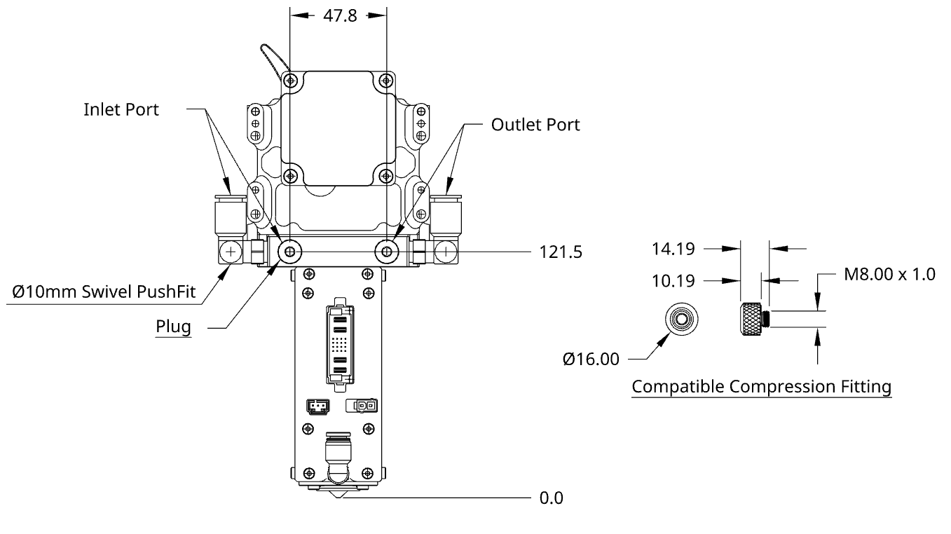
- Recommended Tubing : Ø6.35 mm (1/4") ID x Ø9.53mm (3/8") OD High Temperature Rubber Tubing
- Use one Inlet, one Outlet and plug the others
- The Inlet must be on the opposite side of the Outlet
# Air cooling
The integrated fan on the front housing is in pair with liquid cooling performances. See fan specifications below:
The cooling fan must remain operational at all times while the additive manufacturing machine is in use.
| Working ambient temperature | 0°C ~ 70°C |
|---|---|
| Extruder Cooling | Forced Air with provided 70mm fan |
| Fan Model | PMD2407PTB1-A.(2).GN |
| Rated Voltage | 24 VDC |
| Rated Current | 0.19 A |
| Rated Power | 4.6 W |
| Speed | 5100 RPM |
| Max Air Flow | 1.37 m3/min |
| Acoustical Noise | 46 dBA |
# Part cooling
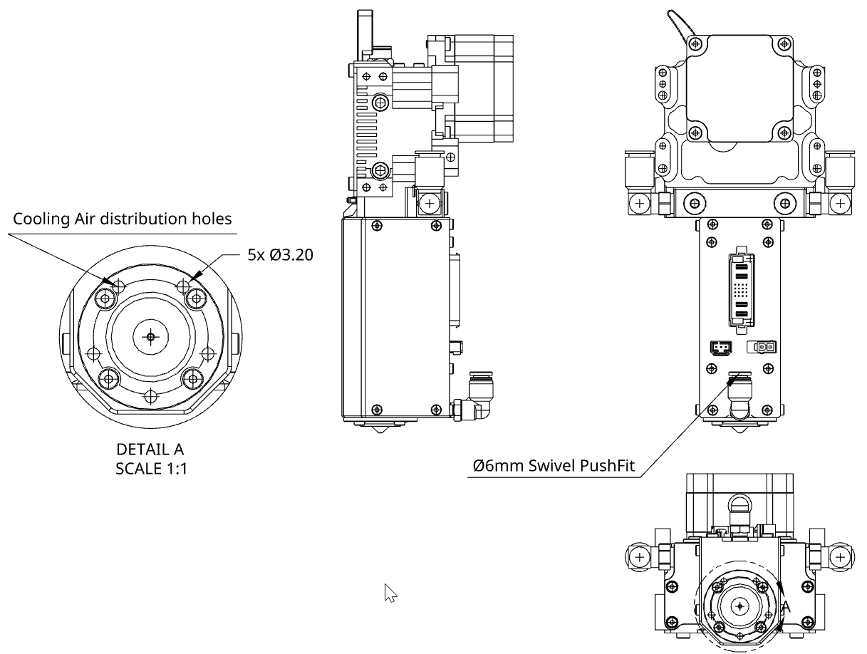
For part cooling, you can either design your own fan duct or you can take advantage of the integrated cooling shroud near the nozzle tip.
Each hole is about 3.2mm diameter.
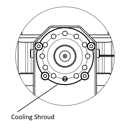
# How to use
The cooling shroud is intended to work with compressed air. You can plug the air compressor tubing in the Pneumatic Push-In fitting at the back of the heatcore.
A 20-30 PSI air compressor should be enough to cool your printed parts.
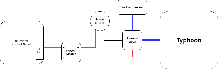
# Using the cooling shroud with your printer board
If you want your 3d printer board to control the air supply, you will have to use a solenoid valve with a power mosfet and plug the relay signal in the FAN input of your 3d printer controller board.
Please refer to the following diagram for connecting the cooling shroud:
# 3D Printer Guideline
The Typhoon has a strong titanium heat barrier. However, this part is still the weak point of the melting zone and can be broken under certain circumstances. Make sure to follow these guidelines to prevent any damage to your Typhoon.
# General
Printing without cooling is only possible with large parts. Thick and large layers take time to cool down, thus requiring you to reduce speed for small parts.
Z homing must be done very carefully due to thermal expansion. For bed leveling with a cold extruder, make sure you compensate the thermal expansion:
- 0.25mm @ 200°C
- 0.41mm @ 300°C
- 0.56mm @ 400°C
Typhoon is designed and tested for 2.85mm filament. Never use “real” 3.00mm filament.
# Use Z lift
Raising the Z axis between each fast-travel is required. It will prevent any collision with the printed part. See the Slicer section for more info.
# Consider thermal expansion
It’s critical to consider the heat cylinder thermal expansion when doing the bed leveling. For example, if leveling at room temperature, the printing head will be 0.25mm lower. See the General topic to learn more.
# Maximum Axis Force
Make sure your axis isn't overpowered. Steppers don’t give feedback on their torque and an overpowered axis could easily damage the Typhoon.The Typhoon can resist a force of 50N at the tip of the nozzle.
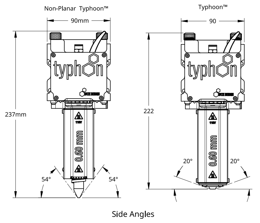
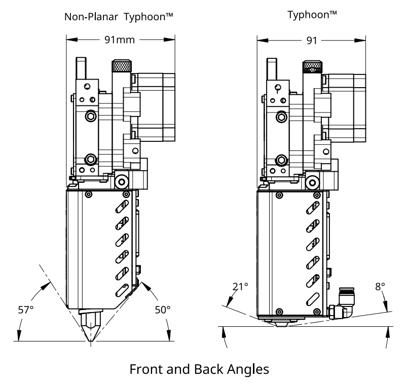
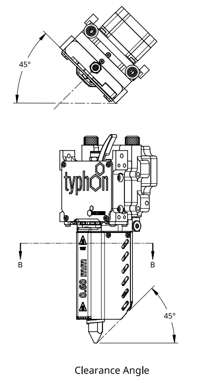
# Non-Planar Typhoon™
The guidelines described in this document regarding the Typhoon™ also apply to the Non-Planar Typhoon™. There is no extra wiring, electronics or mounting to do.
Refer to the drawings and table below for an overall comparison between the Typhoon™ and Non-Planar Typhoon™.
| Typhoon™ | Non-Planar Typhoon™ | |
|---|---|---|
| Maximum recommended nozzle temperature | 450 °C | 450 °C |
| Overall length | 222 mm | 237mm |
| Part cooling | ✅ | ❌ |
| Minimal inclination angle (refer to drawings below) | 8 ° | 45 ° |
WARNING
Hot nozzle. Beware, contact may cause burns.
# Robotic Arm Guideline
If you plan on installing the Typhoon on a robotic Arm, you'll need to get some extra hardware to get the same features as a 3D printer controller. These items are the following:
- A motion planner capable of outputting STEP / DIR pulses for the stepper driver.
- Two (2) PT100 temperature sensor inputs.
- Two (2) digital output to drive the SSRs.
TIP
Dyze Design is now offering an ethernet/ip controller to enable sync between your robot/robot controller and the Typhoon extruder (motor & flow control, heating elements, etc). Contact sales for more information.
# Firmware
# Marlin Firmware
2.0.x# Configuration.h
Set number of extruders:
#define EXTRUDERS 2
Set the correct temperature sensor values. Please refer to Marlin thermal settings (opens new window) to find the correct value based on your amplifier circuit or your actual setup.
#define TEMP_SENSOR_0 68 //could also be 20 or 21. Check the Marlin thermal settings.
#define TEMP_SENSOR_1 68 //could also be 20 or 21. Check the Marlin thermal settings.
Set temperature min temp:
#define HEATER_0_MINTEMP 19
#define HEATER_1_MINTEMP 19
Set temperature max temp:
#define HEATER_0_MAXTEMP 450
#define HEATER_1_MAXTEMP 450
The heaters are very powerful, which is required for engineering and advanced polymers. If you are planning on printing low temperature, reduce the bang_max from 255 to 127.
Set temperature bang_max:
#define BANG_MAX 127
Increase the PID_functional_range:
#define PID_FUNCTIONAL_RANGE 40
Set the base PID values:
 #define DEFAULT_Kp 2.85
 #define DEFAULT_Ki 0.07
 #define DEFAULT_Kd 27.57
Set the extruder steps per mm: Note: {X Axis, Y Axis, Z Axis, E Axis} The value of the XYZ axis may vary and are shown as XXX.XX
#define DEFAULT_AXIS_STEPS_PER_UNIT { XXX.XX, XXX.XX, XXX.XX, 274 }
Set the max feed rate: Note: {X Axis, Y Axis, Z Axis, E Axis} The value of the XYZ axis may vary and are shown as XXX.XX
#define DEFAULT_MAX_FEEDRATE { XXX, XXX, XXX, 50 }
Switch enable logic for the extruder motor:
#define E_ENABLE_ON 1
# Configuration_adv.h
Configure the external stepper driver
#define MINIMUM_STEPPER_POST_DIR_DELAY 500
#define MINIMUM_STEPPER_PRE_DIR_DELAY 500
#define MINIMUM_STEPPER_PULSE 3
#define MAXIMUM_STEPPER_RATE 200000
# RepRap Firmware
TIP
In your configuration file, you should find values similar to the ones below. However, we do recommend that you use the online ReRap Firmware configurator tool (opens new window).
WARNING
The following information is based on Duet 2 and RepRap Firmware 3.x. We strongly suggest that you also read the official Duet/RepRap documentation (opens new window) to make sure you correctly connected and configured your Duet board, PT100 (RTD) amplifier board and RepRap firmware version.
# Config.g
Set the correct temperature sensor values. Please refer to Duet documentation to find the correct value based on your amplifier circuit.
TIP
For the Duet 3 MB6HC, pins spi.cs1 and spi.cs2 should be replaced with spi.cs0 and spi.cs1.
M308 S1 P"spi.cs1" Y"rtd-max31865"    		 	; configure sensor 1 as PT100 on pin e0temp
M308 S2 P"spi.cs2" Y"rtd-max31865"             ; configure sensor 2 as PT100 on pin e1temp
Set temperature max temp:
M143 H0 S450
M143 H1 S450
Set the extruder steps per mm:
M92 XXXX.X YXXX.X ZXXX.X E274.0
Set the max feed rate:
M203 XXXXX YXXXX ZXXXX E3000
Assign heaters 1 and 2 to the same tool:
M563 P0 D0 H1:2 S"Typhoon"
Configure external stepper drivers:
M569 PXXX SXXX R1 T3:3:5:0
The heaters are very powerful, which is required for engineering and advanced polymers. If you are planning on printing low temperature, reduce the maximum PWM by 50%.
Set maximum PWM (Change HX by H0, H1, H2, etc. Based on your heater configuration):
M307 HX S0.50
# Repetier Firmware
TIP
In your configuration file, you should find values similar to the ones below. However, we do recommend that you use the online Repetier Firmware configurator tool (opens new window).
# Configuration.h
Set the correct temperature sensor values. Please refer to Repetier configurator tool (opens new window) to find the correct value based on your PT100 amplifier circuit.
#define EXT0_TEMPSENSOR_TYPE 13
#define EXT1_TEMPSENSOR_TYPE 13
Set temperature min temp:
#define MIN_DEFECT_TEMPERATURE 20
Set temperature max temp:
#define MAXTEMP 450
#define MAX_DEFECT_TEMPERATURE 455
The heaters are very powerful, which is required for engineering and advanced polymers. If you are planning on printing low temperature, reduce the bang_max from 255 to 127.
Set maximum power output:
#define EXT0_PID_MAX 127
#define EXT1_PID_MAX 127
Set the extruder steps per mm:
#define EXT0_STEPS_PER_MM 274
Set the max feed rate:
#define EXT0_MAX_FEEDRATE 200
Switch enable logic for the extruder motor:
#define EXT0_ENABLE_ON 1
# Configuration_adv.h
Configure the external stepper driver
#define STEPPER_HIGH_DELAY 3
#define DIRECTION_DELAY 5
# Using the Typhoon™ extruder
# Slicer and Print Settings
Set vertical lift to at least your layer thickness. For layers of 1.00mm, lift 1.00mm. Slicers aren’t yet optimized for large prints. Many over-extruded sections will be noticeable. Lifting the head will prevent any collision with the printed part.
Wipe nozzle to at least the line width. For a line width of 3.50mm, wipe 3.50mm or greater.
Set the heating to both heaters to the required temperature in the start Gcode script. Make sure to refer to your slicer documentation for variable names.
M109 T0 S[first_layer_temperature]
M109 T1 S[first_layer_temperature]
- Set end script to turn off both extruders:
M104 T0 S0 ; turn off extruder
M104 T1 S0 ; turn off extruder
Output flow and pressure greatly changed depending on the printing speed. To get the best result, keep the output flow steady by keeping the same speed everywhere.
Change the filament setting to 2.85 mm. Typhoon™’s step/mm was calculated using the area of a 2.85 mm filament. You will notice an exaggerated over extrusion with 1.75 mm filament in the slicer’s settings.
# Powering on the unit
Once the unit is mounted, the software is configured and electrical connections are finished. The next step is to power the unit.
While the unit is empty perform the following verification :
- Low speed extrusion command (2 mm/s) - Confirm motor rotation is clockwise when inspecting the motor’s backplate.
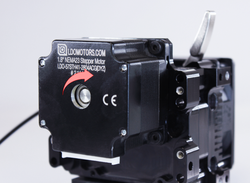
- High speed extrusion command (20 mm/s)- Confirm no grinding noise are audible
- Setpoint to a low temperature (50-75°C)on the first heater
- Make sure the matching sensor reads
- Setpoint to a low temperature (50-75°C) on the second heater
- Make sure the matching sensor reads
# Inserting the Filament
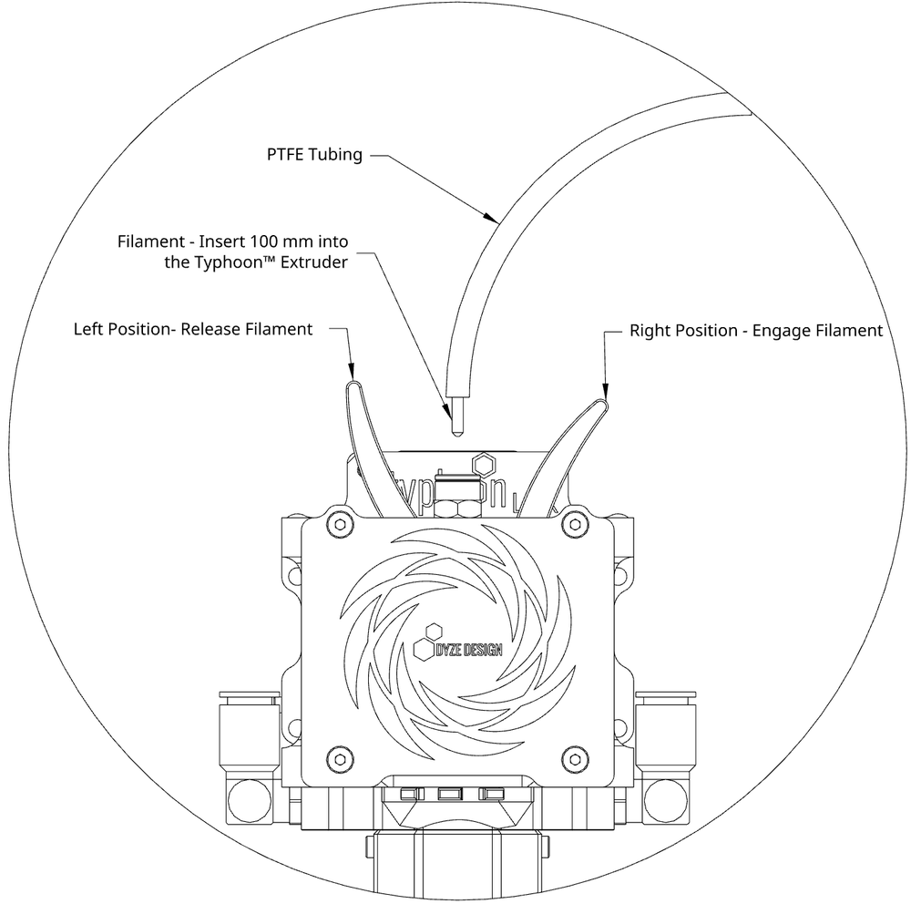
We recommend the use of a PTFE tube or equivalent between the spool and the Typhoon™ Extruder. It will help guide the filament in an efficient way to the inlet of the extruder.
- Remove the PTFE tube from the pushfit
- Cut the tip of the filament
- Release the driving wheels by pulling the lever to the left
- Insert the filament approximately 100 mm until it stops
- Engage the driving wheels by pushing the lever to the right
- Insert the PTFE tube into the pushfit
# Printing Speed
The tables below gives you the maximum volumetric flow for a specific polymer according to the nozzle size. If your polymer isn't there, please contact us (opens new window) and we'll do our best to add it to this list. We suggest using the Recommended volumetric flow as a starting point, but we also provided the Absolute maximum volumetric flow for reference.
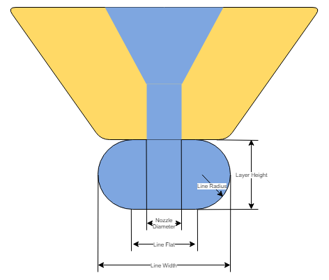
Depending on your slicer configuration, a bit of math is required in order to find the right printing speed. The important parameters from your slicer are:
- Layer height
- Line width
For simplification, we won't consider the round edges for our speed calculation, but you can read more here (opens new window) if you are interested.

# Example Speed Calculation
Let's consider an example with the following parameters:
- Filament: ASA
- Typhoon nozzle: 2.50mm
- Layer height: 2.00mm
- Line width: 6.00mm
Considering the recommended table, ASA using a 2.50mm nozzle has a volumetric flow of 182 mm³/s.

The printing speed should be under 15.2 mm/s. It might seems slow, but remember that it is still 182 mm³/s, which is close to 1kg / h.
# Recommended volumetric flow (mm³/s)
| Polymer | Company | Test Temperature (C) | 2.50mm | 1.80mm | 1.20mm | 0.90mm | 0.60mm |
|---|---|---|---|---|---|---|---|
| PCL | Filaments.ca | 140 | 74 | 47 | 31 | 25 | 21 |
| LLDPE | Filaments.ca | 200 | 142 | 112 | 86 | 71 | 55 |
| PLA | Overture | 210 | 128 | 104 | 79 | 67 | 51 |
| PLA-N | 3D Filkemp | 215 | 113 | 94 | 70 | 55 | 35 |
| NinjaFlex | TPU 3.00mm | 230 | 30 | 25 | 20 | 18 | 15 |
| ABS | Filaments.ca | 230 | 145 | 125 | 86 | 70 | 60 |
| TPU 91A | Filaments.ca | 240 | 79 | 72 | 59 | 51 | 48 |
| TPE 90A | Filaments.ca | 240 | 79 | 68 | 53 | 45 | 33 |
| TPE 85A | Filaments.ca | 240 | 90 | 70 | 52 | 41 | 28 |
| nGen | colorFabb | 240 | 153 | 149 | 99 | 81 | 68 |
| PP | FormFutura | 240 | 199 | 170 | 144 | 126 | 98 |
| HIPS | Kodak | 240 | 195 | 167 | 136 | 113 | 90 |
| PA6 | Kodak | 250 | 95 | 85 | 77 | 70 | 65 |
| D3 woodfill | Laywoo | 250 | 216 | 203 | 180 | 164 | 138 |
| PETG | Overture | 250 | 137 | 127 | 101 | 81 | 72 |
| ASA | Filaments.ca | 250 | 182 | 158 | 114 | 86 | 72 |
| PC CPE | Filaments.ca | 260 | 139 | 120 | 107 | 90 | 82 |
| Ultem PEI | Filaments.ca | 330 | 75 | 73 | 68 | 63 | 59 |
# Absolute maximum volumetric flow (mm³/s)
| Polymer | Company | Test Temperature (C) | 2.50mm | 1.80mm | 1.20mm | 0.90mm | 0.60mm |
|---|---|---|---|---|---|---|---|
| PCL | Filaments.ca | 140 | 90 | 60 | 45 | 38 | 27 |
| LLDPE | Filaments.ca | 200 | 158 | 136 | 109 | 85 | 70 |
| PLA | Overture | 210 | 142 | 115 | 88 | 78 | 60 |
| PLA-N | 3D Filkemp | 215 | 125 | 104 | 85 | 75 | 65 |
| NinjaFlex | TPU 3.00mm | 230 | 37 | 29 | 22 | 20 | 17 |
| ABS | Filaments.ca | 230 | 161 | 138 | 95 | 85 | 70 |
| TPU 91A | Filaments.ca | 240 | 88 | 80 | 65 | 57 | 53 |
| TPE 90A | Filaments.ca | 240 | 87 | 76 | 59 | 50 | 38 |
| TPE 85A | Filaments.ca | 240 | 103 | 80 | 62 | 50 | 42 |
| nGen | colorFabb | 240 | 170 | 165 | 110 | 90 | 75 |
| PP | FormFutura | 240 | 222 | 200 | 169 | 140 | 110 |
| HIPS | Kodak | 240 | 216 | 185 | 151 | 125 | 100 |
| PA6 | Kodak | 250 | 109 | 96 | 85 | 78 | 75 |
| D3 woodfill | Laywoo | 250 | 240 | 225 | 200 | 183 | 173 |
| PETG | Overture | 250 | 153 | 141 | 112 | 90 | 80 |
| ASA | Filaments.ca | 250 | 202 | 175 | 126 | 95 | 80 |
| PC CPE | Filaments.ca | 260 | 154 | 133 | 119 | 100 | 91 |
| Ultem PEI | Filaments.ca | 330 | 83 | 82 | 75 | 70 | 65 |
# Flow to RPM
For some applications, such as robotic arms, it's easier to configure the motor RPM rather than using the length of material to extrude, as seen in traditional 3D printer controllers. The following table lists the parameters for the F-RPM factor, which is the Flow to RPM variable discussed in our blog post here. (opens new window) The blog is writte for pellets extruder in mind, but is also valid for filament extruders such as the Typhoon.
Since the Typhoon is pushing a filament, the FRPM is the same for most filaments:
FRPM = 0.81
For very flexible filaments (around 85A), a lower FRPM can be used as a starting point, due to the slipping:
FRPM_Flexible = 0.76
# Maintenance & Troubleshooting
# Clogged Nozzle
WARNING
Never drill any parts from the Typhoon. Some parts are hardened, others have a specific surface roughness. The drill could damage or get broken and stuck inside the unit.
# Causes
Clogging can be caused by a few factors. Make sure you understand which one is causing the issue and solve it before attempting a new print.
- Bad slicer settings
- Too high retraction. Make sure you are not pulling the molten filament too high. Try reducing it or disable it to see if the problem is solved.
- Too high volumetric flow. Make sure you aren't asking too much of the Typhoon. Thick and wide lines are misleading since a slow printing speed can still represent a high volumetric throughput.
- Bad filament conditions.
- Filament is not dry. A filament containing a lot of moisture will foam at the entry and greatly increase the friction. The print quality will also greatly suffer.
- Wrong temperatures. Usually, because of the very long melting zone, lower temperature can lead to better results.
- Bad filament quality. Always choose well rated polymers, and reliable brands. Paying a little more can save you a lot of trouble.
- Bad extruder and heatbreak cooling.
- Water is not flowing. Make sure the water is flowing properly. Validate my probing the extruder body temperature.
- Water is too hot. Think about changing the radiator or the fan for a bigger one.
# Solution 1: Temporary extrude hotter
- Raise the temperature by steps of 10°C.
- Wait until the setpoint is reached.
- Send a slow extrusion command such as the one below. Please note that trying to push the filament by hand is worthless. The extruder has much more force.
G0 F60 E25
- Repeat until the extruder is unclogged or the temperature is too high.
- Perform a cleaning procedure
# Solution 2: Remove the filament using a hot air gun
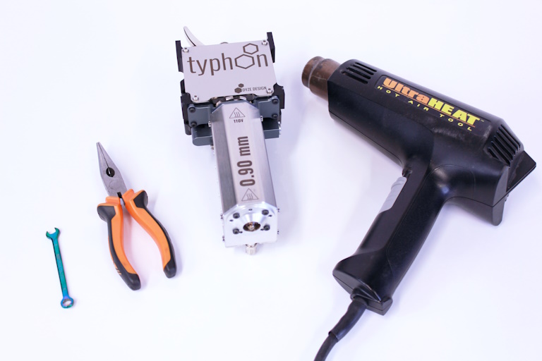
# Tools Needed:
- 6 mm Wrench
- Long Nose Pliers
- Clogged Typhoon
- Heat Gun
- Set the target temperature to 0°C and wait until the unit has cooled.
- Loosen the filament lever.
- Remove the HeatCore using the 6 mm wrench. Slowly lower it to reveal the filament.
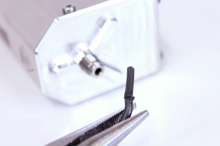
- Observe the filament. Check for any larger, deformed sections near the threaded part of the HeatCore or grinding marks from the driving section.
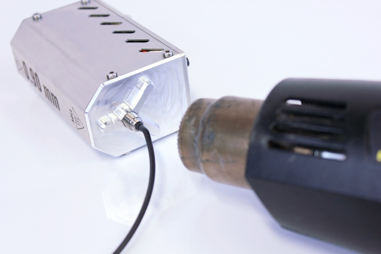
- Use a heat gun, pointing it towards the threads of the HeatCore to soften the filament stuck in that region. Be careful not to overheat it—the filament should become soft, but not molten.
- Slowly pull the filament out of the heat break using the long nose pliers.
- Reinstall the HeatCore back into the Typhoon, and start printing!
# Gears
The gears can be accessed by removing two screws on the top. You should use those holes to grease the gears.
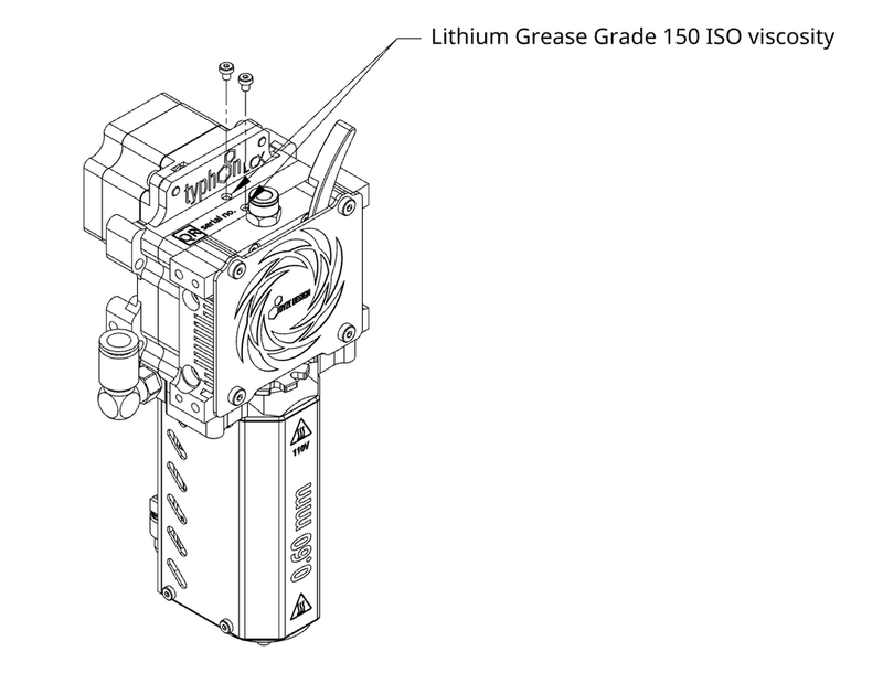
Remove the filament while greasing the gears and let the motor run freely while gently applying grease.
We suggest using white lithium grease. The Typhoon comes pre-greased with white lithium grease, ISO Viscosity Grade of 150.
We suggest using a small sized grease gun such as the Astro Mini Grease Gun (opens new window).
# Periodic Inspection
To ensure longevity of the gearbox and its components, periodic in depth inspection and maintenance is suggested. Inspect all the gears and housing periodically. To do so, disassemble the housings from the front to expose the gears. Clean most of the old grease with towels.
Gears with excessive wear marks or worn down teeth should be replaced.
See exploded view (opens new window) to help with disassembly and spare parts numbers
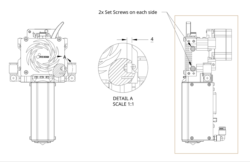
# Pressure adjustment
To make sure the filament has the proper pressure from the driving wheels, the four M10 set screws depths need to be the same. Factory setting is 4 mm from the edge of the housing.
# Dehumidifying Maintenance Routine
Diagnosing the Problem
To diagnose the insulation, use a multimeter set to 200MΩ. Measure the resistance between one of the heater's power cables and the ground. A healthy reading should be above 1MΩ or show an "Open Circuit" reading.
If you get a low resistance reading, it's most likely due to moisture. This is a common issue that you can resolve by gently drying the heater.operating temperature.
The Drying Process
Follow these steps to safely remove moisture from the heater:
Turn on the printer and set the hot end temperature to 50-75°C. The goal is a gentle, sustained warmth. Maintain this temperature for at least 2 hours to allow the moisture time to fully evaporate.
Next, increase the hot end temperature to 95°C and hold it there for at least 2 more hours.
Use your multimeter to check the resistance again. When the multimeter shows an "open circuit" or "OL" reading, the heater is dry.
Once the heater is dry, you can safely run it at its normal operating temperature.
# Risk Assessment
A full risk assessment document is available for the Typhoon™ Extruder. This document states which inherent risks remain for the operation of the extruder. Trained personnel using this machinery are required to familiarize themselves with the assessment.
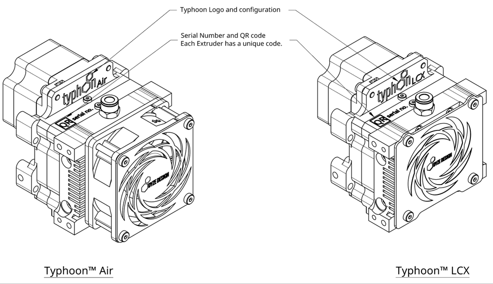
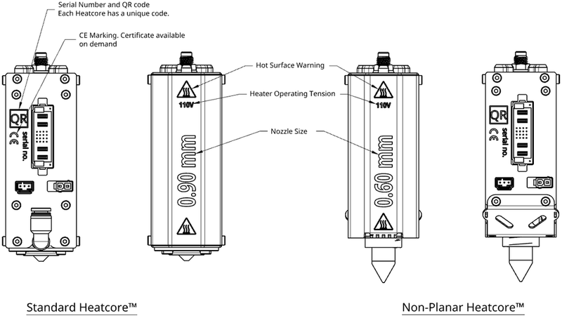
# Typhoon™ Extruder authenticity and informative markings
A genuine Typhoon™ Extruder will have permanent markings etched on the housing of the Extruder, on the front shield of the Heatcore and the backplate of the Heatcore. A complete Typhoon™ Extruder consists of 2 serial numbers. One for the Extruder and one for the Heatcore™