# SENTINEL™ Filament Detector
WARNING
Please ensure that your 3d printer is equipped with an LCD controller, otherwise, Sentinel™ will not work. Sentinel™ can work without LCD if you have Octoprint/OctoPi.
# General
| Sentinel™ Version | Minimum Filament Diameter | Maximum Filament Diameter |
|---|---|---|
| 1.75mm | 1.70mm | 1.80mm |
| 2.85mm | 2.78mm | 2.92mm |
The Filament Sentinel™ will detect the presence of your filament.Each Sentinel™ will draw 31mA. It requires 5V for power. The output logic is 3.3V and works with both 3.3V and 5V based microcontrollers.
| Filament | Logic | Green LED |
|---|---|---|
| Present | HIGH – 3.3V | ON |
| Absent | LOW – 0V | OFF |
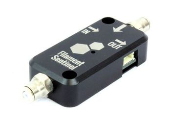
The IN label stands for a signal entry. This connector will only be used if you are daisy-chaining Sentinel™ together.
The OUT label stands for a signal exit. This connector will always be used, either for connecting to your mainboard, or to a daisy-chained Sentinel™.
# Where to install SENTINEL™ on your printer
# After the spool
Make sure it is stable. Attach it to the spool holder, on the table, or on anything that is fixed.
# Before your extruder
Fix it on your printer, before the extruder.
WARNING
Don’t install between your extruder and hotend. The extruder won’t push the filament past the Sentinel™, no detection will occur!
# PTFE tubing
When replacing the stock 4mm PTFE tubing with longer tubes, make sure the new tubing are at the right depth. Check the table below:
| Fitting | Inserted length | Notes |
|---|---|---|
| Top | 46mm (1.75mm) / 52mm (2.85mm) | As deep as it can get into the Sentinel™ |
| Bottom | 17mm | Flush with the fitting. Do not compress the dust filter. |
# Wiring
| Cable Color | Connection |
|---|---|
| Black | Ground |
| Blue | Signal |
| Red | +5V |
# Connections
TIP
The “In” connector is only required when you have more than 1 Sentinel™.
| Label | Connection | Cable |
|---|---|---|
| In | Sentinel™ (Daisy-chain) | Daisy-chain cable (short) |
| Out | Main Board | Main cable (long) |
# Pins
The easiest pins to use for the filament Sentinel™ are the followings:
- Servo pins
- Endstop pins
It is also possible to use the following:
- Expansion pins
- Communication pins
# Connections examples
# Servo/Endstop
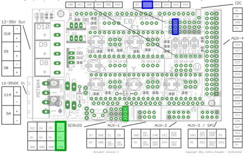
Servo pins always have the right pins: 5V, Ground and Signal.
Most endstop pins will have the same 3 pins, and sometimes only Signal and Ground. If you only have these two, there should be a 5V somewhere else on your main board.
# Pins examples
Choosing the Endstop pin from this example lead to the Digital Pin 2 as [DIGITAL PIN INPUT].
Choosing the Servo pin from this example lead to the Digital Pin 4 as [DIGITAL PIN INPUT].
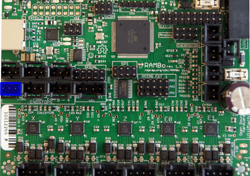
Rambo is a little bit less detailed on their general diagram. To find the pins association, the page RamBo Development (opens new window) must be accessed.
Choosing the X Max Endstop pin from this example lead to the Digital Pin 24 as [DIGITAL PIN INPUT].
# Expansion
Some boards are very limited and a deeper understanding is required for connecting the Sentinel™ properly.
The Melzi (opens new window) is a good example of a minimalistic board as there are no additional servo pins nor endstop pins.
Communication pins and extension pins will be used instead.
The following documentation is required to determine the pin configuration:
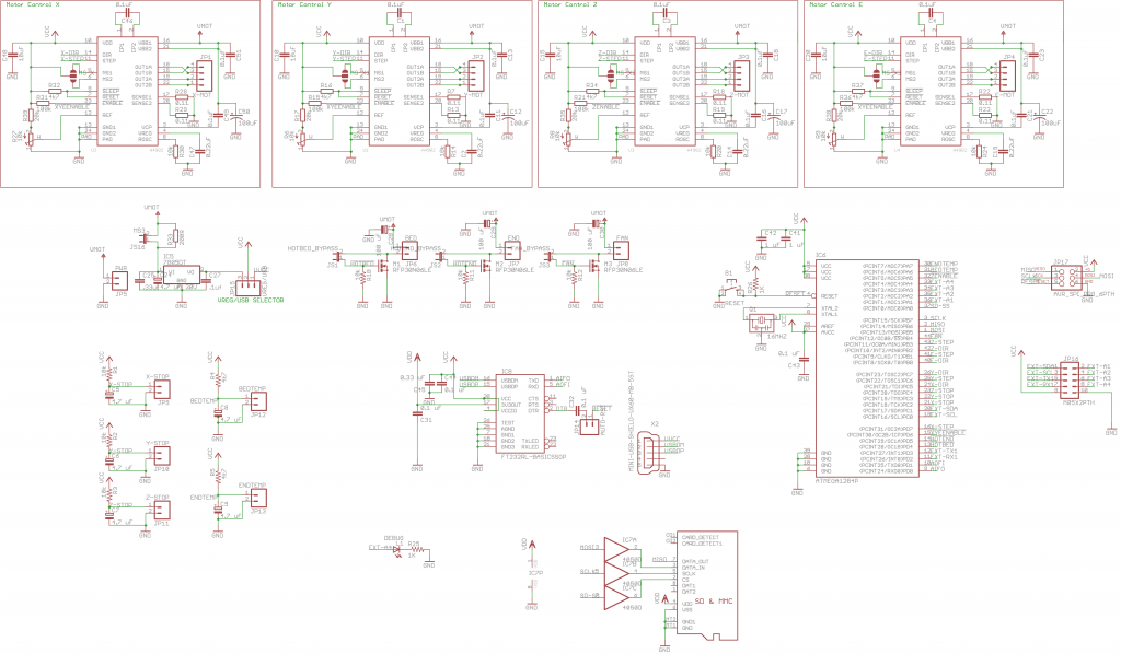
In this example, expansion pins from JP16 can work, or any communication pins from JP17 too. Let’s consider EXT-A4 as our signal pin, as an analog pin can be used as a digital pin. Also, by choosing this pin, we will still be able to use the communication pins for any further add-on.
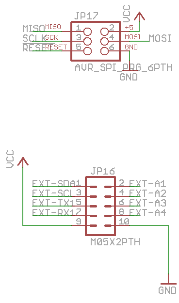
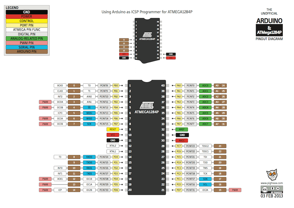
The EXT-A4 pin corresponds to the (PCINT4/ADC4)PA4 pin on the MCU (Microcontroller unit).
From the image below, you can see that the PA4 pin is either the Analog Pin 4 or the Digital Pin 28. We will consider the Digital Pin 28 for the firmware configuration [DIGITAL PIN INPUT].
# Firmware configuration
# Marlin Firmware 1.1.0-RC7 or newer
WARNING
Make sure your firmware has the filament runout feature, you need Marlin 1.1.0-RC7 or newer. If you are using an older version, contact your 3D printer manufacturer or update your firmware configuration manually.
# Configuration.h
In the configuration.h file, find and comment out this line:
#define FILAMENT_RUNOUT_SENSOR //Uncomment
If you are having trouble with false alarms, you can add the following line:
#define FILAMENT_RUNOUT_THRESHOLD 100
# Auto-park feature 1.1.2 or newer
Starting version 1.1.2, Marlin also introduced an auto-park feature. To enable this feature, comment out this line:
#define NOZZLE_PARK_FEATURE //Uncomment
# Pins_[BOARD NAME].h
Find the pins_ .h file corresponding to your board (RAMPS, Melzie, MinRambo, etc).
Uncomment this line:
#define FIL_RUNOUT_PIN XX //Replace XX with your digital pin input number
# Configuration_adv.h
Find the configuration.h file.
WARNING
Between version 1.1.0 and version 1.1.2, the codebase was changed a bit. Please refer to the corresponding version below.
# Version 1.1.0-RC7
In configuration_adv.h, find and comment out this line:
#define FILAMENT_CHANGE_FEATURE //Uncommment
# Version 1.1.2
In configuration_adv.h, find and uncomment those line:
#define ADVANCED_PAUSE_FEATURE //Uncomment
#define PARK_HEAD_ON_PAUSE
#define HOME_BEFORE_FILAMENT_CHANGE //if you see this line, you can also uncomment
# Repetier Firmware
WARNING
Make sure your firmware has the filament runout feature. You need minimally Repetier 0.92.9. If you are using an older version, contact your 3D printer manufacturer or update your firmware configuration manually.
# Configuration.h
In the configuration.h file, find these lines and replace [DIGITAL PIN INPUT] with your pin number.
#define EXT0_JAM_PIN [DIGITAL PIN INPUT]
#define JAM_ACTION 1
# RepRap Firmware
# Simple pause
# 1.18 and older
Settings > System Editor > config.g
M581 T1 E0 S0 C0
# 1.19 and newer
Settings > System Editor > config.g
M591 D0 P1 C[Your Pin] S1
See Duet M591 (opens new window) for more details.
# Custom macro trigger
Settings > System Editor > config.g
M581 T2 E0 S0 C0
Settings / System Editor / trigger2.g
Put any custom code you’d like to do once your extruder runs out of filament. Example:
M83 ; relative extruder moves
G1 E-10 F600 ; retract 10mm of filament
G91 ; relative positioning
G1 Z2 F360 ; lift Z by 2mm
G90 ; absolute positioning
G1 X00 Y00 F6000 ; go to X=10 Y=10
# Setup on a Raise3D printer
WARNING
The Raise3D requires 1 Sentinel™ per extruder. Make sure each one has the primary cable. The daisy-chain cables aren’t working with the firmware configuration.
# Install the Sentinel™ in your printer
The Sentinel™ comes with 2 M3x10 screws. You can drill or tap holes where you want your Sentinel™ to be fixed.
TIP
Make sure the two Sentinel™ aren’t too far away from your main board. The primary cable is 1000mm in length.
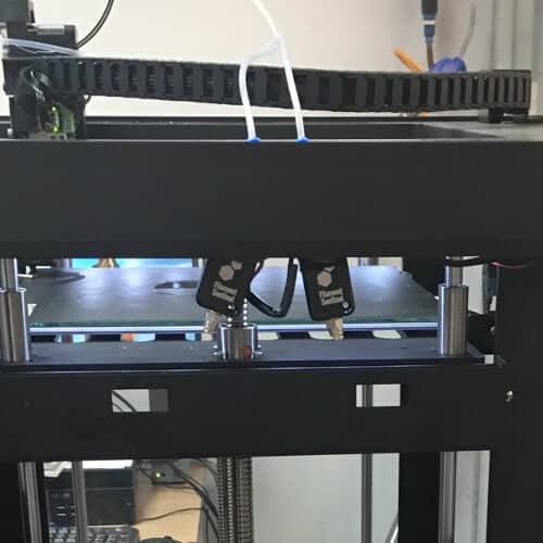
The two Sentinels are placed close to each other. They are easy to access for filament change and they are close enough to the main circuit board.
# Connect each Sentinel to your Rumba
# Connect your first Sentinel
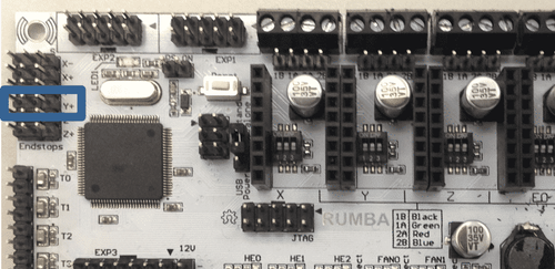
This Sentinel™ will be linked to your first extruder. Connect the 3 wires to Y+ pins from your Rumba.
| Sentinel™ Cable | Rumba Board |
|---|---|
| Red (+5V) | Y+,+ |
| Black (Ground) | Y+,- |
| Blue (Signal) | Y+,S |
# Connect your second Sentinel™
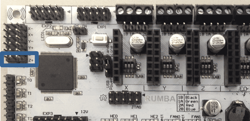
This Sentinel will be linked to your second extruder. Connect the 3 wires to Z+ pins from your Rumba.
| Sentinel™ Cable | Rumba Board |
|---|---|
| Red (+5V) | Z+,+ |
| Black (Ground) | Z+,- |
| Blue (Signal) | Z+,S |
# Flash your firmware
Marlin 1.1.7 Raise3D Source Code (opens new window)
Marlin 1.1.7 Raise3D Compiled (opens new window)
Raise3D LCD updater (opens new window)
# Configure your firmware
# Slicer
Go to your profile setting in your slicer
Edit the start g-code
Add the following line to activate the filament Sentinel™
F0 S1 P1If you have a second extruder, also add the following code:
F1 S1 P1
# LCD
- Go to advanced settings
- Activate the filament monitor option
# Maintenance
# Cleaning your SENTINEL™
The sentinel™ clean your filament before it gets to your extruder and hotend. The filter should be checked every 1 kg to 10 kg, depending on your set-up.
Loosen the bottom fitting
Using a 10mm wrench, loosen the bottom fitting.
Remove the filter
Using a small tweezer, remove the filter from the housing.
Clean the filter
Remove the debrits and dusts that are stuck inside the filter. If the filter appears damaged, replace it with a new one.
Install the filter
Using a small tweezer, install the filter back in the housing.
Tighten the bottom fitting
Using a 10mm wrench, tighten the bottom fitting. Make sure the PTFE tubing does not compress the filter too much.