# PT100 Amplifier Board
# What's included
| Item | Quantity |
|---|---|
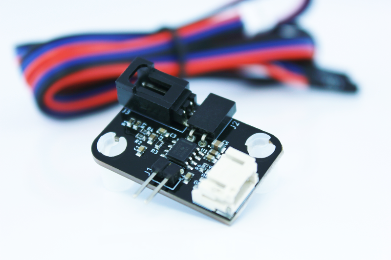
| PT100 Analog Amplifier PCB | 1 |
| Sensor cable | 1 |
# What’s required
- PT100 Sensor (you can buy one here (opens new window))
- A compatible 3D Printer Controller (Ramps 1.4, SKR boards, MKS boards, Smoothieboard, ReArm, etc.)
WARNING
This PT100 Amplifier board is not compatible with DUET boards. To use PT100 sensors with DUET boards and RepRap firmware, you need to buy DUET PT100 daughter boards (opens new window).
# Specifications
| Features | Specification |
|---|---|
| Compatible firmwares | Marlin 2.0.9.4 (or above)(https://github.com/DyzeDesign/Marlin/releases/latest (opens new window)) Klipper (https://github.com/Klipper3d/klipper/ (opens new window)) |
# Electrical Specifications
| Parameter | Condition | Min | Typical | Max | Unit |
|---|---|---|---|---|---|
| Power supply (Vcc) | Controller logic voltage: 3.3V | - | 3.3 | - | V |
| Controller logic voltage: 5V | - | 5 | - | V | |
| Current consumption | 0.5 | - | 1.5 | mA | |
| Output Tension (Vout) | 0.15 | - | Vcc-0.15 | V |
# Output voltage lookup table
| Temperature (°C) | PT100 value(Ω) | Output voltage (V) @ 3.3V | Output voltage (V) @ 5V |
|---|---|---|---|
| 0 | 100 | 0.8822 | 1.3367 |
| 20 | 107.794 | 0.9497 | 1.4389 |
| 40 | 115.541 | 1.0165 | 1.5401 |
| 60 | 123.242 | 1.0827 | 1.6405 |
| 80 | 130.897 | 1.1484 | 1.7400 |
| 100 | 138.505 | 1.2135 | 1.8387 |
| 120 | 146.068 | 1.2780 | 1.9364 |
| 140 | 153.584 | 1.3420 | 2.0333 |
| 160 | 161.054 | 1.4054 | 2.1294 |
| 180 | 168.478 | 1.4683 | 2.2246 |
| 200 | 175.856 | 1.5305 | 2.3190 |
| 220 | 183.188 | 1.5923 | 2.4125 |
| 240 | 190.473 | 1.6535 | 2.5052 |
| 260 | 197.712 | 1.7141 | 2.5971 |
| 280 | 204.905 | 1.7742 | 2.6882 |
| 300 | 212.052 | 1.8338 | 2.7784 |
| 320 | 219.152 | 1.8928 | 2.8679 |
| 340 | 226.206 | 1.9513 | 2.9565 |
| 360 | 233.214 | 2.0093 | 3.0443 |
| 380 | 240.176 | 2.0667 | 3.1314 |
| 400 | 247.092 | 2.1236 | 3.2176 |
| 420 | 253.962 | 2.1801 | 3.3031 |
| 440 | 260.785 | 2.2360 | 3.3878 |
| 460 | 267.562 | 2.2913 | 3.4717 |
| 480 | 274.293 | 2.3462 | 3.5549 |
| 500 | 280.978 | 2.4006 | 3.6373 |
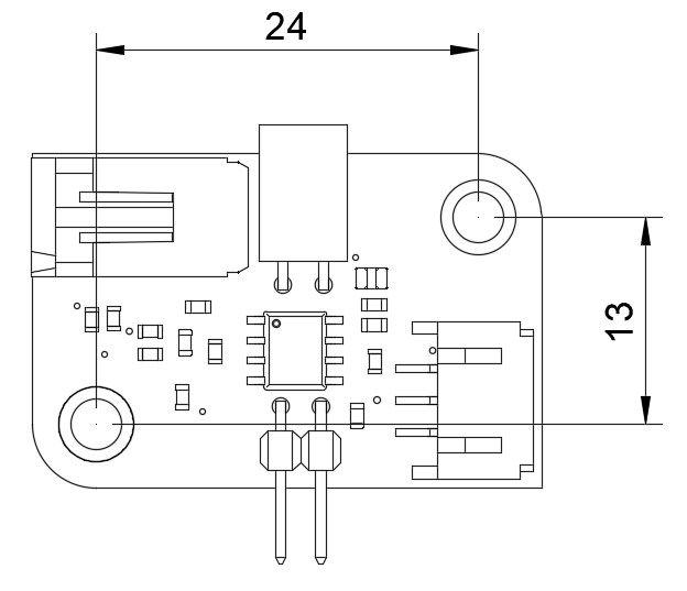
# Installation / Mounting
You can refer to this drawing for easy mounting in your printing environment:
# Wiring
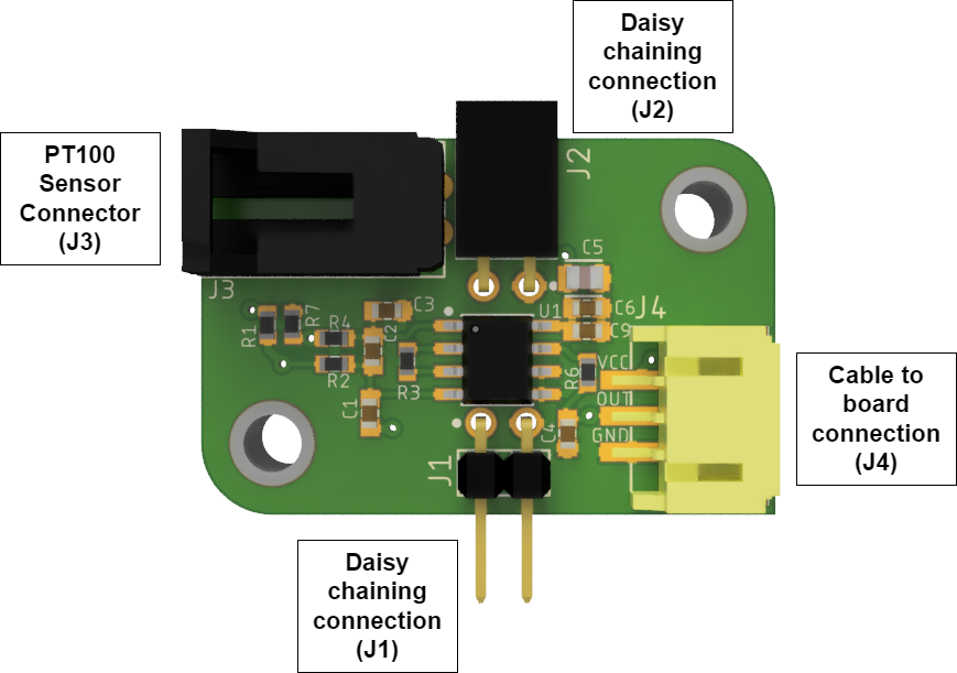
TIP
Multiple PT100 amplifier boards can be connected together (daisy-chained). Simply insert the male daisy chaining connectors (J1) inside the female daisy chaining connection (J2) of your other PT100 amplifier board.
# Power supply selection
- The power supply should be chosen according to the logic tension of your controller.
- If you are daisy chaining more than one PT100 Analog Amplifier, only the first one should be connected to Vcc. For the other, connect only the signal pin (blue wire). If you have ground pins available near the analog inputs on your board, you can connect those too.
# PT100 Sensor Connection
- The PT100 Sensor must be connected to connector J3
- The connector mate with a PH3-3 connector from JST Sales Amarica Inc. or a standard dupont connector with a pitch of 100MIL.
# Controller Board Connection
| Cable Color | Connection |
|---|---|
| Red | Vcc |
| Blue | Signal |
| Black | GND |

- Connect Vcc wire to 3.3V or 5V depending on the logic tension use by your controller
- Connect the GND wire to a GND pin
- Connect the Signal wire to an analog input.
WARNING
Make sure not to use a thermistor input, since those pins usually have a pullup resistor and will not work with the PT100 Analog Amplifier
# Example for RAMPS 1.4
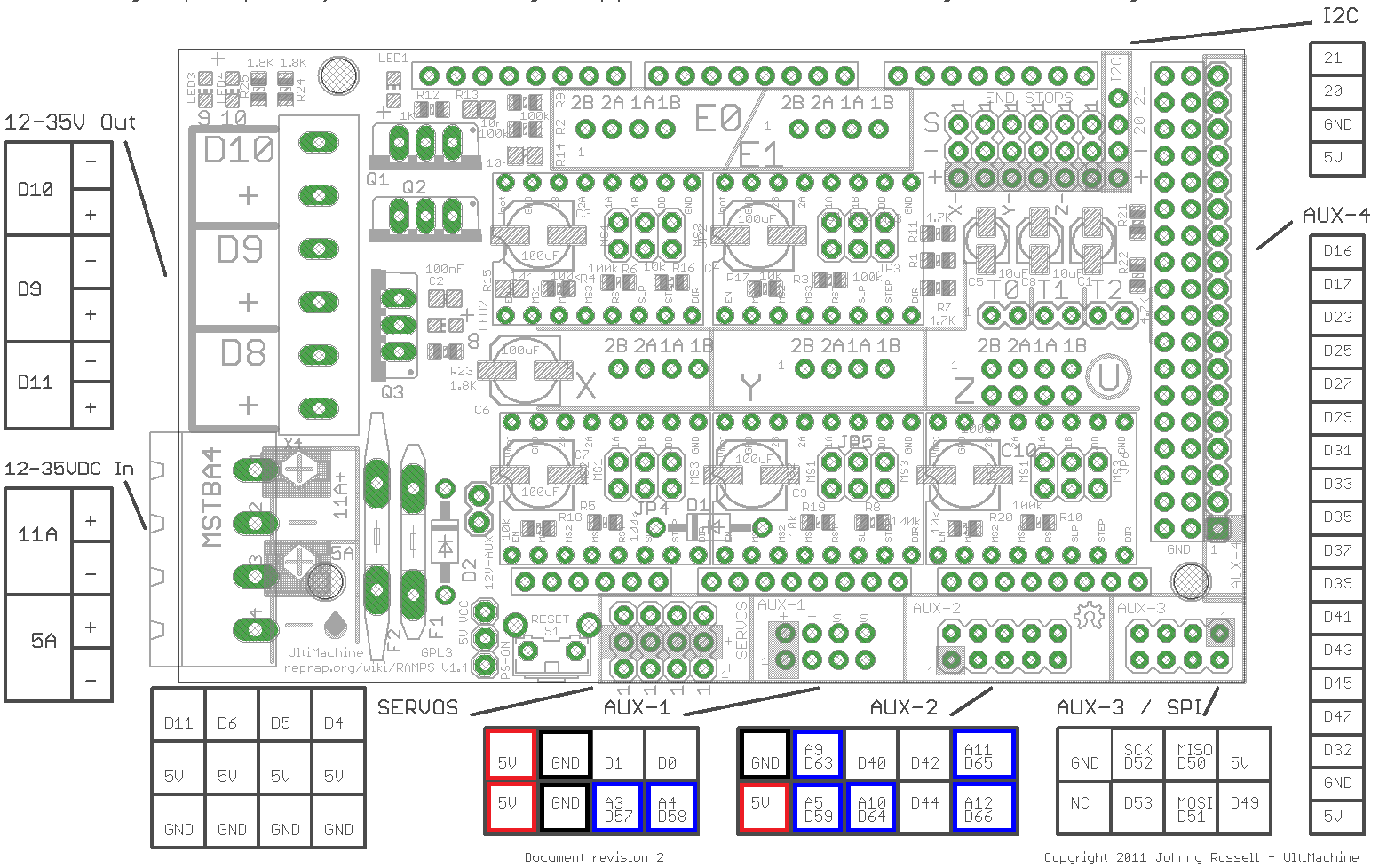
Signal input pins for RAMP 1.4 :
- A3
- A4
- A5
- A9
- A10
- A11
- A12
# Firmware
# Marlin Firmware
The PT100 Analog Amplifier is supported by the official distribution of Marlin since release 2.0.9.4
# Configuration.h
Configure the temperature sensor (lines 540-553):
#define TEMP_SENSOR_0 68
Add the following line to specify the pin use for the signal:
#define TEMP_0_PIN 3
# Klipper
Open the printer.cfg file. You will need to configure a custom ADC temperature sensor. The resulting sensor can be used as a sensor_type in a heater section.
# Create ADC temperature sensors
In your printer.cfgfile, add two new sections with the below code:
WARNING
Be sure to place these sections in the config file above its first use in a heater section (usually the [extruder] section).
[adc_temperature pt100_3v3]
#temperature1:
#voltage1:
#temperature2:
#voltage2:
#...
#   A set of temperatures (in Celsius) and voltages (in Volts) to use
#   as reference when converting a temperature. A heater section using
#   this sensor may also specify adc_voltage and voltage_offset
#   parameters to define the ADC voltage (see "Common temperature
#   amplifiers" section for details). At least two measurements must
#   be provided.
temperature1: 0
voltage1: 0.8822
temperature2: 20
voltage2: 0.9497
temperature3: 40
voltage3: 1.0165
temperature4: 60
voltage4: 1.0827
temperature5: 80
voltage5: 1.1484
temperature6: 100
voltage6: 1.2135
temperature7: 120
voltage7: 1.2780
temperature8: 140
voltage8: 1.3420
temperature9: 160
voltage9: 1.4054
temperature10: 180
voltage10: 1.4683
temperature11: 200
voltage11: 1.5305
temperature12: 220
voltage12: 1.5923
temperature13: 240
voltage13: 1.6535
temperature14: 260
voltage14: 1.7141
temperature15: 280
voltage15: 1.7742
temperature16: 300
voltage16: 1.8338
temperature17: 320
voltage17: 1.8928
temperature18: 340
voltage18: 1.9513
temperature19: 360
voltage19: 2.0093
temperature20: 380
voltage20: 2.0667
temperature21: 400
voltage21: 2.1236
temperature22: 420
voltage22: 2.1801
temperature23: 440
voltage23: 2.2360
temperature24: 460
voltage24: 2.2913
temperature25: 480
voltage25: 2.3462
temperature26: 500
voltage26: 2.4006

[adc_temperature pt100_5v]
temperature1: 0
voltage1: 1.3367
temperature2: 20
voltage2: 1.4389
temperature3: 40
voltage3: 1.5401
temperature4: 60
voltage4: 1.6405
temperature5: 80
voltage5: 1.7400
temperature6: 100
voltage6: 1.8387
temperature7: 120
voltage7: 1.9364
temperature8: 140
voltage8: 2.0333
temperature9: 160
voltage9: 2.1294
temperature10: 180
voltage10: 2.2246
temperature11: 200
voltage11: 2.3190
temperature12: 220
voltage12: 2.4125
temperature13: 240
voltage13: 2.5052
temperature14: 260
voltage14: 2.5971
temperature15: 280
voltage15: 2.6882
temperature16: 300
voltage16: 2.7784
temperature17: 320
voltage17: 2.8679
temperature18: 340
voltage18: 2.9565
temperature19: 360
voltage19: 3.0443
temperature20: 380
voltage20: 3.1314
temperature21: 400
voltage21: 3.2176
temperature22: 420
voltage22: 3.3031
temperature23: 440
voltage23: 3.3878
temperature24: 460
voltage24: 3.4717
temperature25: 480
voltage25: 3.5549
temperature26: 500
voltage26: 3.6373
# Define the custom ADC sensor
In your printer.cfg file, locate and modify the sensor_type from the [extruder] section as follows:
TIP
Replace the data in """___""" by your own
sensor_type: """ your custom ADC sensor defined before, ex: pt100_5v """
#   One of the custom ADC sensor you added before: pt100_5v or pt100_3v3. The sensor to be added is determined by the controller logic voltage 3.3V or 5V.
sensor_pin:  """ the pin name where the Dyze PT100 amplifier board is plugged """
#   Analog input pin connected to the sensor. This parameter must be
#   provided.
#adc_voltage: 5.0
#   The ADC comparison voltage (in Volts). The default is 5 volts.
#voltage_offset: 0
#   The ADC voltage offset (in Volts). The default is 0.
# Maintenance
No maintenance required