
# Installation / Mounting
The mainboard and its modules are equipped with DIN rail clips on the back of the PCB, allowing easy installation on standard 35mm DIN rails. For alternative mounting, the DIN rail clips can be removed, and the boards can be secured using standoffs and the designated hole pattern. Always use the same holes previously utilized by the DIN rail clips for mounting.
For hole positions, head to our drawing repository (opens new window), where you’ll find:
- 2D drawing with hole position in PDF format
- 3D models in STEP format
| ⚠️ | Handle the PCB with care. Do not twist or bend the PCB. Failing to do so can damage the solders. |
|---|
# Mounting the board on a DIN Rail
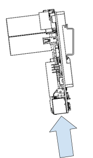 | 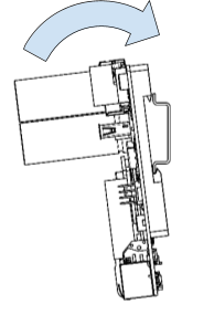 | 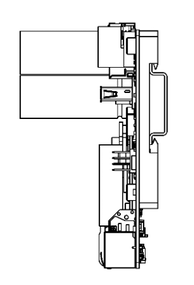 |
|---|---|---|
| Insert the bottom part of the clip to the DIN Rail and push up to compress the spring loaded mechanism | Tilt the top portion of the PCB towards the DIN Rail | Release the PCB and check if it is properly seated. |
# Mounting the board using screws
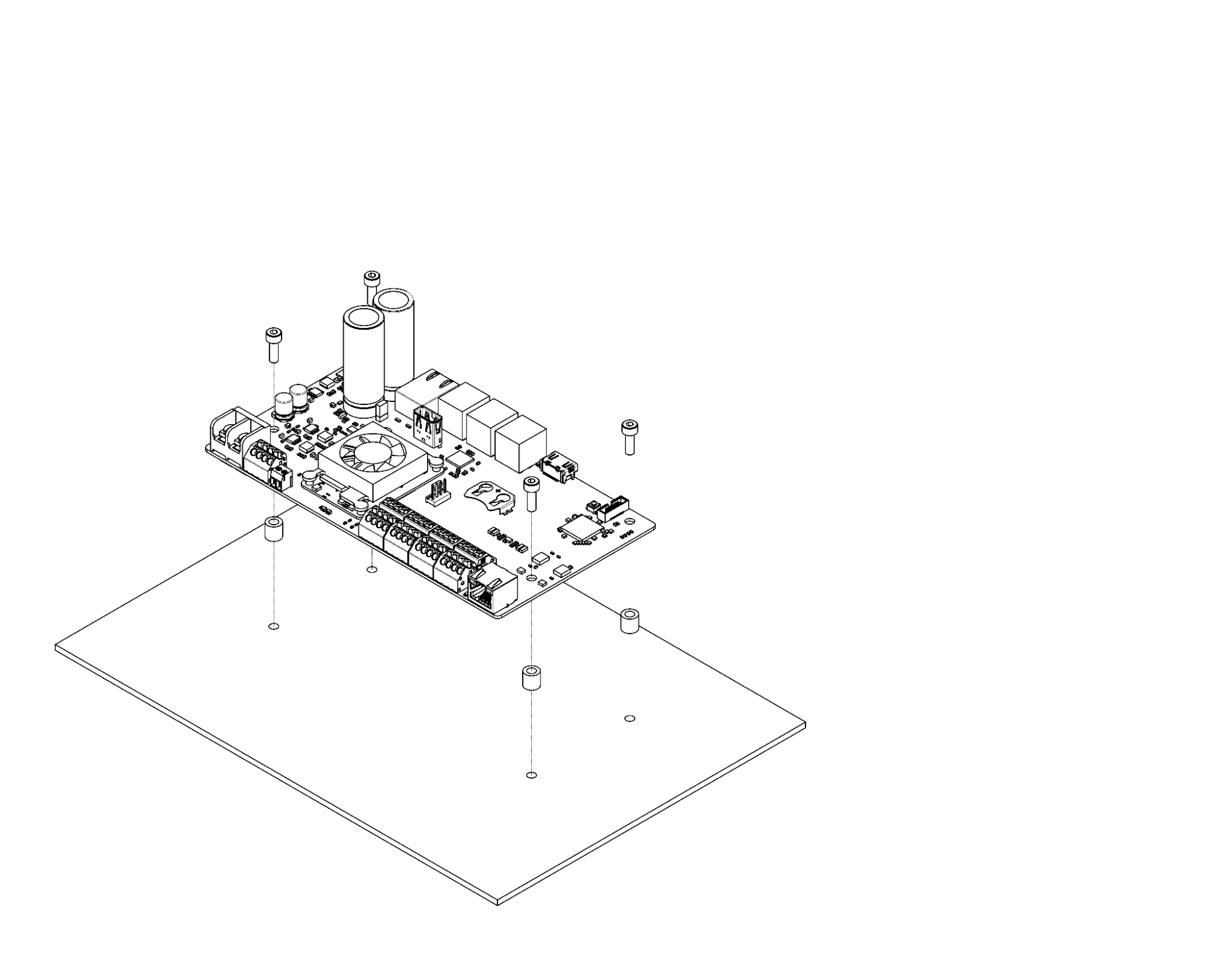 | The board can be mounted using 4 screws (M4) and spacers. The screws and spacers are not included. The spacers should be at least 8mm height. |
|---|