
# Aurora
# Overview
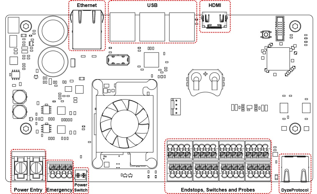
The Aurora has many inputs and outputs and it is critical to understand their purpose and usage before attempting to wire the board. Each connection will be described in detail.
- Ethernet: Used for direct internet connection if the Wireless option isn’t used
- USB: USB ports for storage, accessories like mouse, webcam and keyboard
- HDMI: Used for display
- Power Entry: Main power input for the Aurora
- Emergency: Emergency button wiring
- Power Switch: Power button wiring
- Endstop, Switches and Probes: Fast reactive inputs for homing and instantaneous triggering
- DyzeProtocol: Aurora peripherals network for modules
| ⚠️ | Both Ethernet and DyzeProtocol are using a RJ45 connector. Make sure not to mistake them as they are not electrically compatible. The DyzeProtocol has a red tape over it to help differentiate. |
|---|
# Cables and connectors
| Connection | Connector | Suggested Wire |
|---|---|---|
| Ethernet | RJ45 | CAT5 or better |
| USB | USB Type A | Any |
| HDMI | HDMI Standard | Any |
| Power Entry | Screw Terminal | 12-22 AWG |
| Emergency | Push-in Spring Connector | 16-24 AWG |
| Power Switch | Screw Terminal | 18-26 AWG |
| Endstop, Switches and Probes | Push-in Spring connector | 16-24 AWG |
| DyzeProtocol | RJ45 Shielded | Cat5E or better |
# Detailed connections
# Ethernet
Gigabit Ethernet is supported through a standard RJ45 connector.
# USB
6 ports are available for accessories such as touchscreen, mouse, keyboard and camera.
# HDMI
One HDMI 2.0 capable of 4K (3840 x 2160) resolution up to 60 FPS. Is it advised to use a monitor of 7 in or bigger, as the interface isn’t ideal for small screens.
# Power Entry
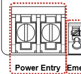
| 24V | GND |
|---|---|
| +24V only | Power ground |
| ⚠️ | The power must not be interrupted by the emergency switch. The Aurora must stay powered while other devices are shut down for security. |
|---|
# Emergency
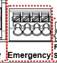
| IN + | 24V | GND | IN- |
|---|---|---|---|
| Isolated positive input, must be connected | This 24V can be used to feed the IN+ input. | This can be used to feed the IN- input. | Isolated negative input, must be connected |
# Wiring Example 1
| Emergency stop wiring example #1, when motor drivers are connected to a different power supply with an isolated ground path, the emergency stop input is electrically isolated from the mainboard power and ground. | 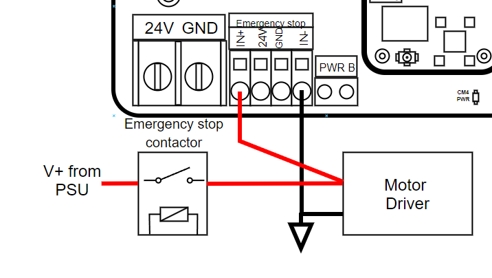 |
|---|
# Wiring Example 2
| Emergency stop wiring example #2, when motor drivers are connected to the same power supply as the mainboard. | 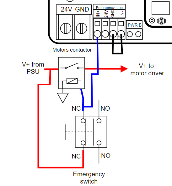 |
|---|
# Power Switch
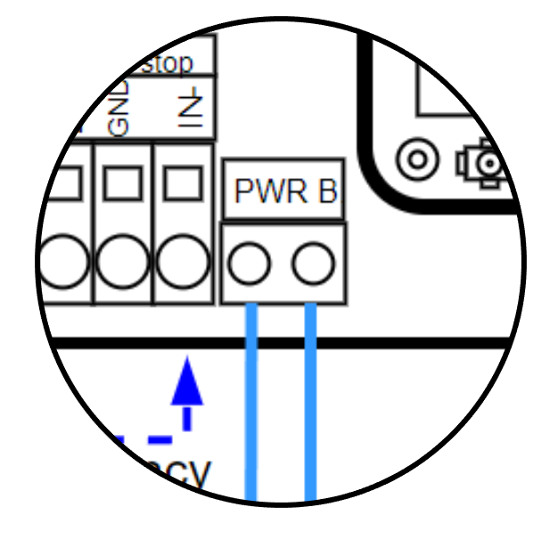
A normally closed (NC) SPST switch should be connected to this terminal block. If the power button is not required, this input must be left unconnected. The button will turn on and turn off the mainboard.
# Endstop, Switches and Probes
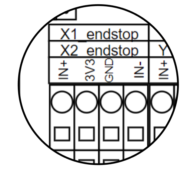
| IN + | 3V3 | GND | IN- |
|---|---|---|---|
| Could be used to acquire an active high signal. from a switch or an active sensor. Must be left unconnected if it's not used. | Provide a power source to supply a switch or an active sensor. | Provide a ground source to supply a switch or an active sensor. | Could be used to acquire an active low signal, from a switch or an active sensor. Must be left unconnected if it's not used. |
# DyzeProtocol
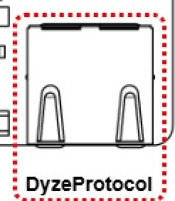
Cables for DyzeProtocol should be wired according to the standard T-568A RJ-45 and the cable be CAT5E or greater. The DyzeProtocol should be daisy-chained from one module to the other.
An ending connector must be installed at the end of this chain, this connector will terminate the chain and ensure that the signal integrity of the line is preserved.
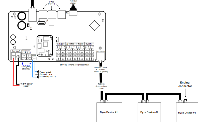
| ⚠️ | The modules can be connected in any order via DyzeProtocol to best suit your wiring and layout. |
|---|
# LEDs
# UPS LEDs
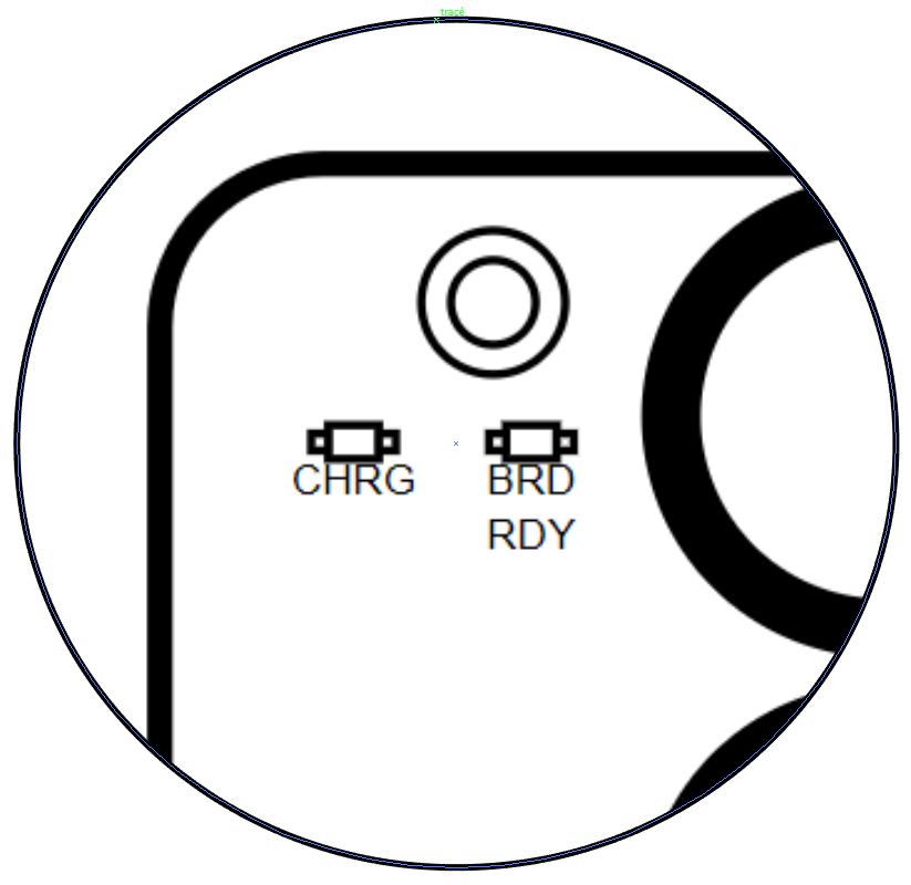
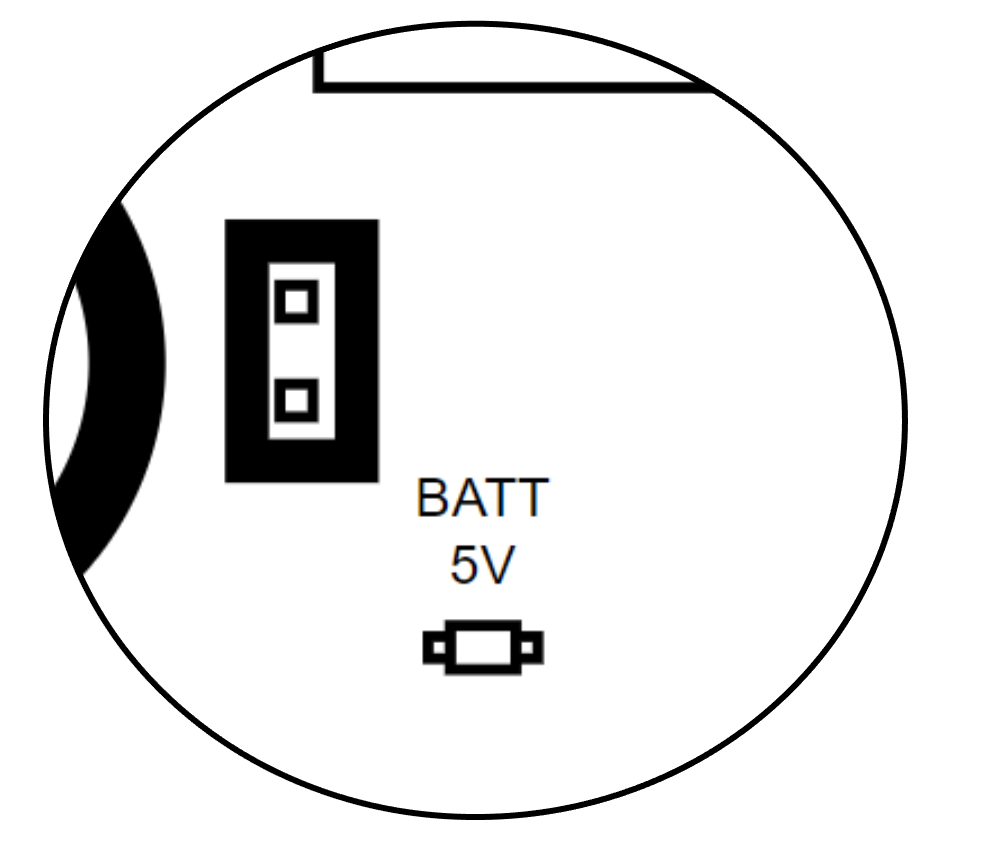
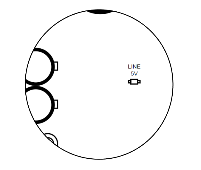
| CHRG | BRD RDY | BATT 5V | LINE 5V |
|---|---|---|---|
| On when the power bank is charging. | On when the mainboard is ready to operate. A first cycle of charging has to be completed. | On when a power down is detected, the battery backup is activated and the shutdown cycle is engaged. | On when the power line regulator is active. |
# CM4 LEDs
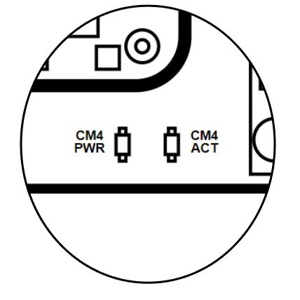
| CM4 PWR | CM4 ACT |
|---|---|
| On when the CM4 is powered. | On when activity (read/write) is detected on the CM4 memory. |