
# Servo Module
The Servo Module is a high-performance drive designed to work with three-phase brushless DC (BLDC) motors equipped with quadrature encoders. It communicates with the Dyze Mainboard via the DyzeProtocol, enabling seamless integration into Dyze-based systems. The module offers precise motor control, encoder feedback for accurate positioning, and various configuration options to optimize performance for specific applications. The Servo Module is an essential component for applications requiring high-precision motion control, such as robotics, CNC machining, and automated manufacturing processes.
# Overview
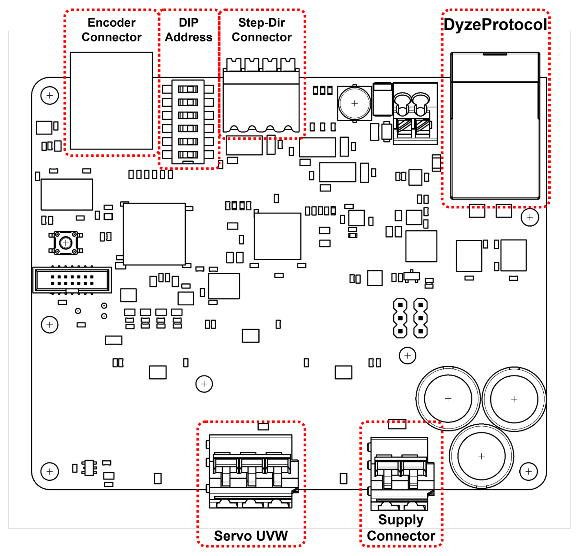
# Cables and connectors
| Connection | Connector | Suggested Wire |
|---|---|---|
| Encoder | RJ50 | 26 AWG stranded |
| Set-Dir | Screwless Terminal | 16-24 AWG |
| DyzeProtocol | RJ45 Shielded | Cat5E or better |
| Servo UVW | Screwless Terminal | 12-28 AWG |
| Supply | Screwless Terminal | 12-28 AWG |
# Detailed connections
# Encoder
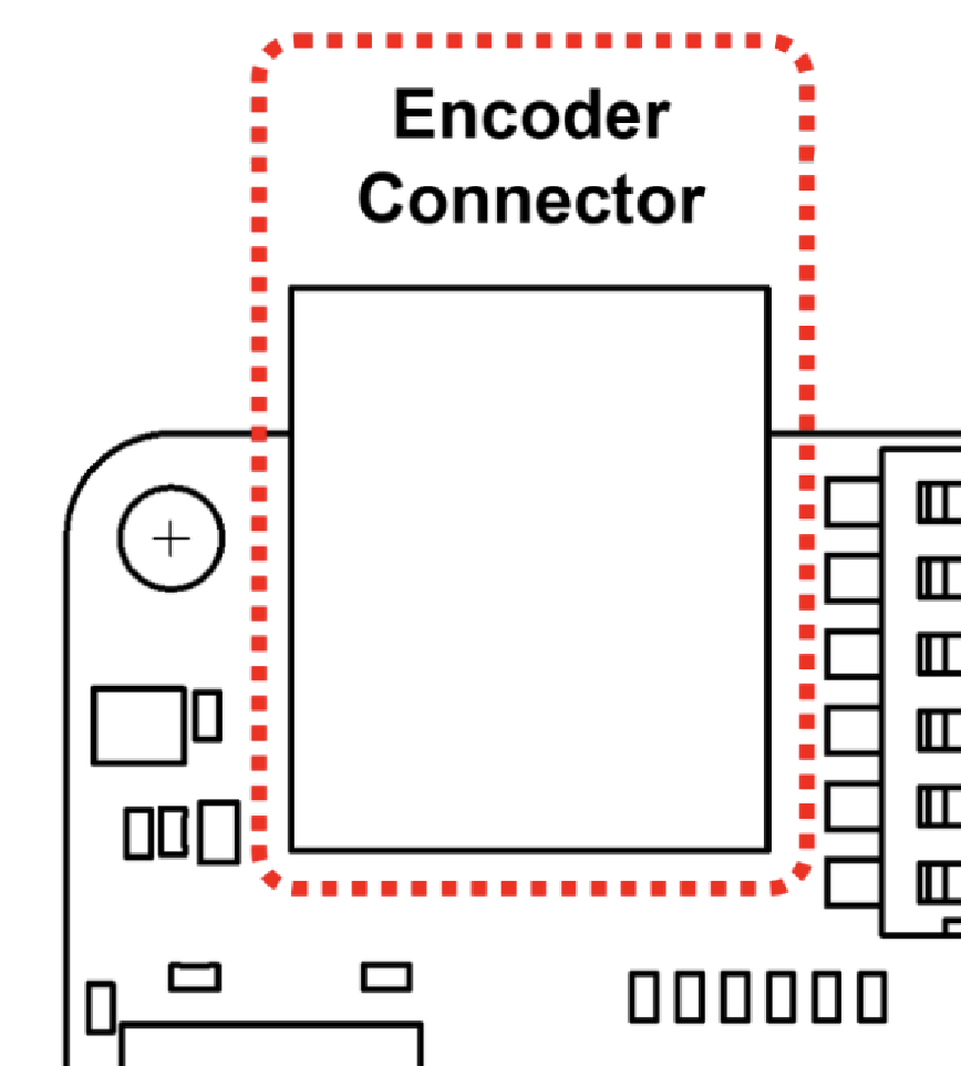
| RJ50 Encoder Connector |
|---|
| Pin 1: GND Pin 2: ENC A + Pin 3: ENC A - Pin 4: RTD - Pin 5: Index - Pin 6: Index + Pin 7: RTD + Pin 8: ENC B + Pin 9: ENC B - Pin 10: 24V |
# Step-Dir
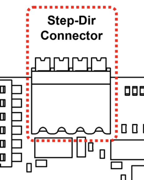
| Step-Dir Connector | Details |
|---|---|
| Pin 1: Enable | Enable input (optional) Stepper will be active when left unconnected 3.3V to 5V |
| Pin 2: Dir | Direction input 3.3V to 5V |
| Pin 3: Step | Step/pulse input 3.3V to 5V |
| Pin 4: Gnd | Signal ground, must be connected to the controller ground |
# Series resistor
| ⚠️ | Add inline series resistors if connecting the stepper to a higher control voltages than 5V. |
|---|
| 12V | 24V | 48V |
|---|---|---|
| 680Ω | 1.5KΩ | 2.7KΩ |
# DyzeProtocol
See DyzeProtocol.
# Servo UVW
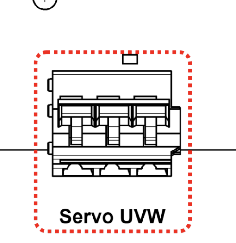
| Servo UVW | Details |
|---|---|
| Pin 1: U | Power Output for Phase U |
| Pin 2: V | Power Output for Phase V |
| Pin 3: W | Power Output for Phase W |
# Supply
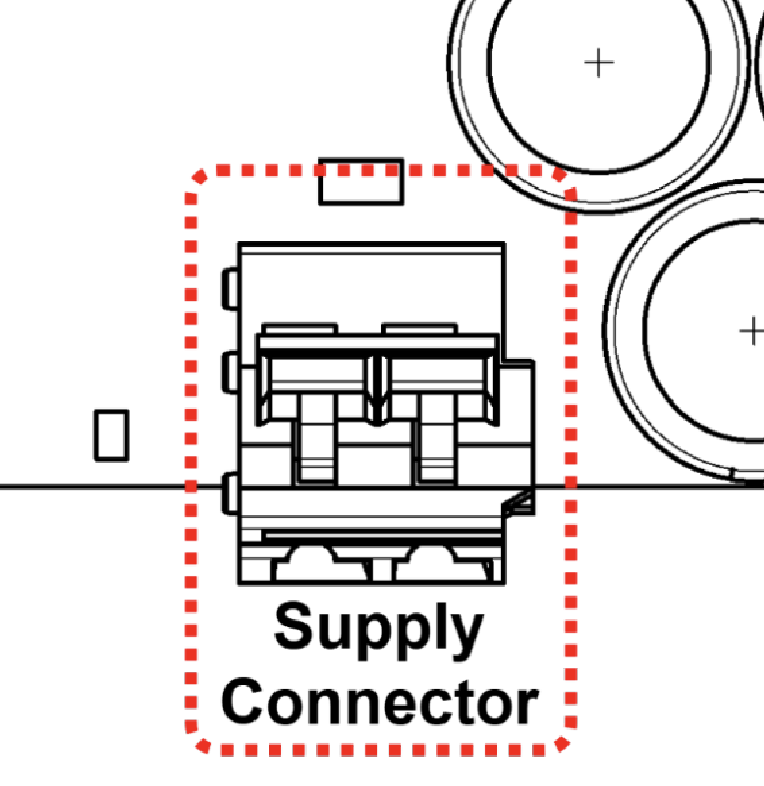
| Supply | Details |
|---|---|
| Pin 1: + | Power Input V+ |
| Pin 2: - | Power Input V- |
# LEDs
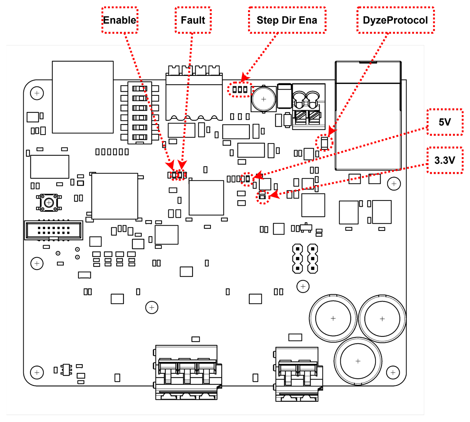
The Step-Dir Module features a few LEDs to indicate status information.
- 5V and 3.3V green LEDs: should be fully lit when the Step-Dir Module is powered by 24VDC.
- Dyze Protocol (DP) yellow LED: blinks when connected to the Dyze Protocol
- Enable Red LED: When the module is enabled
- Fault Red LED: When the module is in fault
# DIP Switches
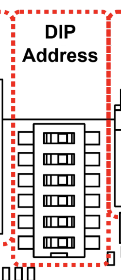
Use the DIP switches on the Servo Module to set its ID according to the following table.
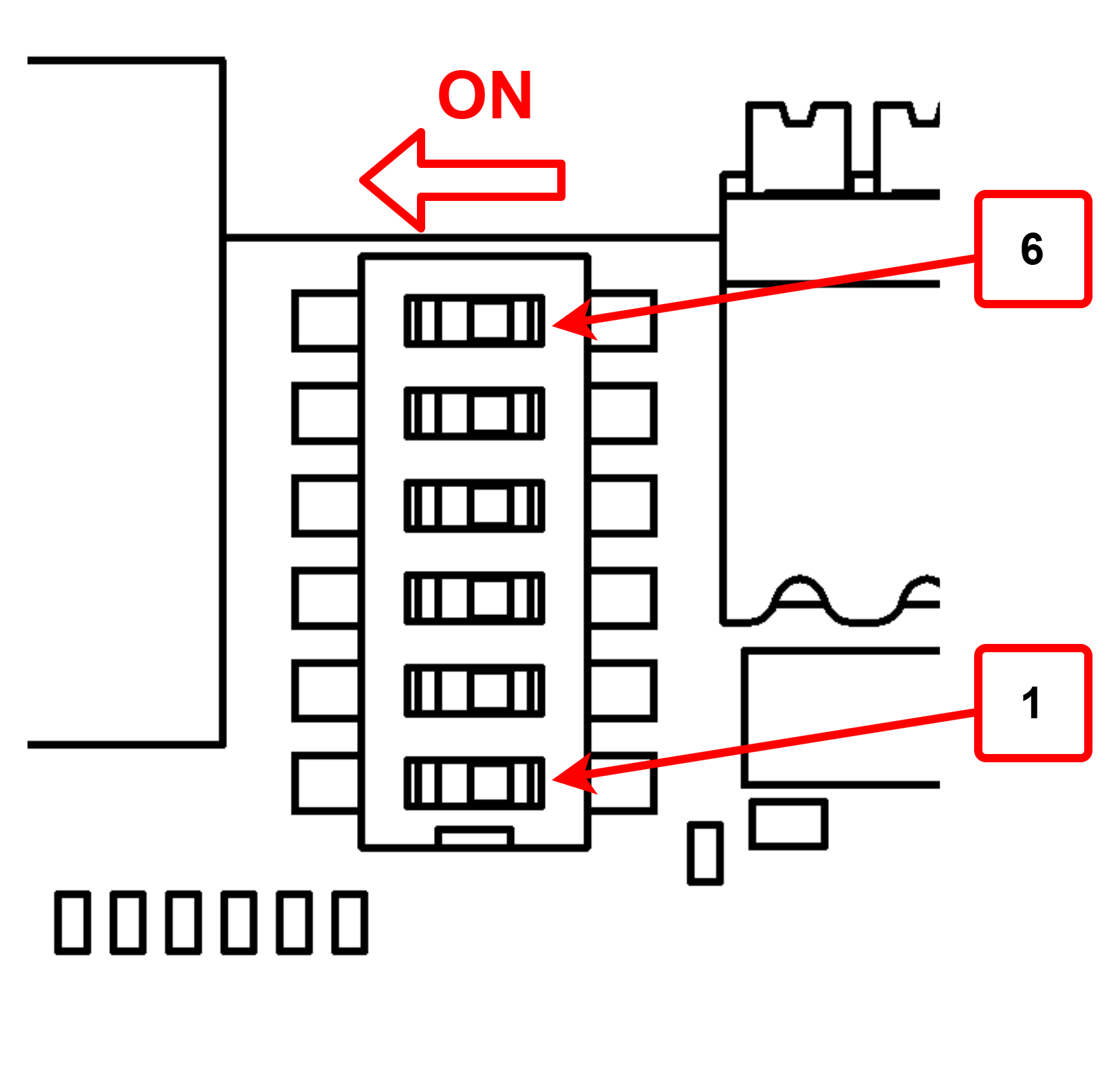
| S1 | S2 | S3 | S4 | S5 | S6 | ID |
|---|---|---|---|---|---|---|
| OFF | OFF | OFF | OFF | OFF | ON | 1 |
| OFF | OFF | OFF | OFF | ON | OFF | 2 |
| OFF | OFF | OFF | OFF | ON | ON | 3 |
| … | … | … | … | … | … | … |
| ON | ON | ON | ON | OFF | ON | 62 |
| ON | ON | ON | ON | ON | OFF | 63 |
| ON | ON | ON | ON | ON | ON | 64 |
← Step-Dir Module UPS →