# Power&Thermal Submodule
The Power&Thermal Submodule is capable of driving loads between 12V and 24V with a maximum current of 10A. The power stage is fully isolated from the control stage and it is thus possible to use isolated power supplies to power the connected loads.
There are two types of Power&Thermal Submodules, which are dependent on the kind of thermal sensor used. The compatibility of the submodule should be marked on the bottom side of the PCB. Else, it is possible to determine which submodule is which by looking at components populating it. Refer to the following table for better understanding.
| PT100 | Thermistor |
|---|---|
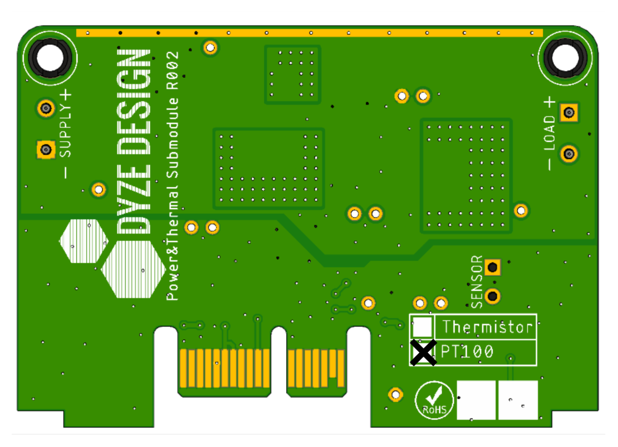 | 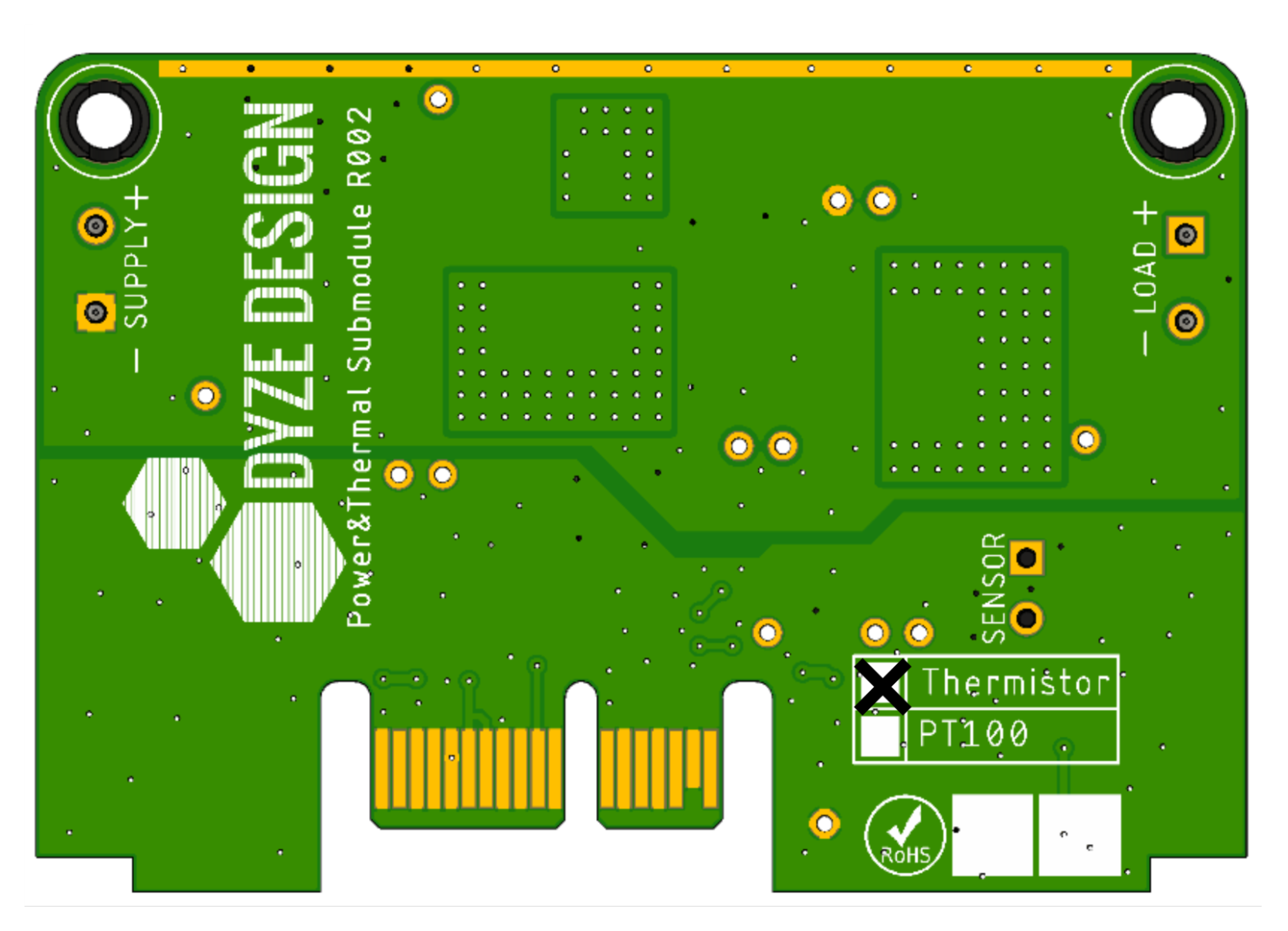 |
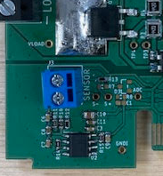 U2 IC and corresponding circuitry present | 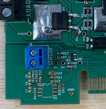 U2 IC not present |
# Overview
# Cables and connectors
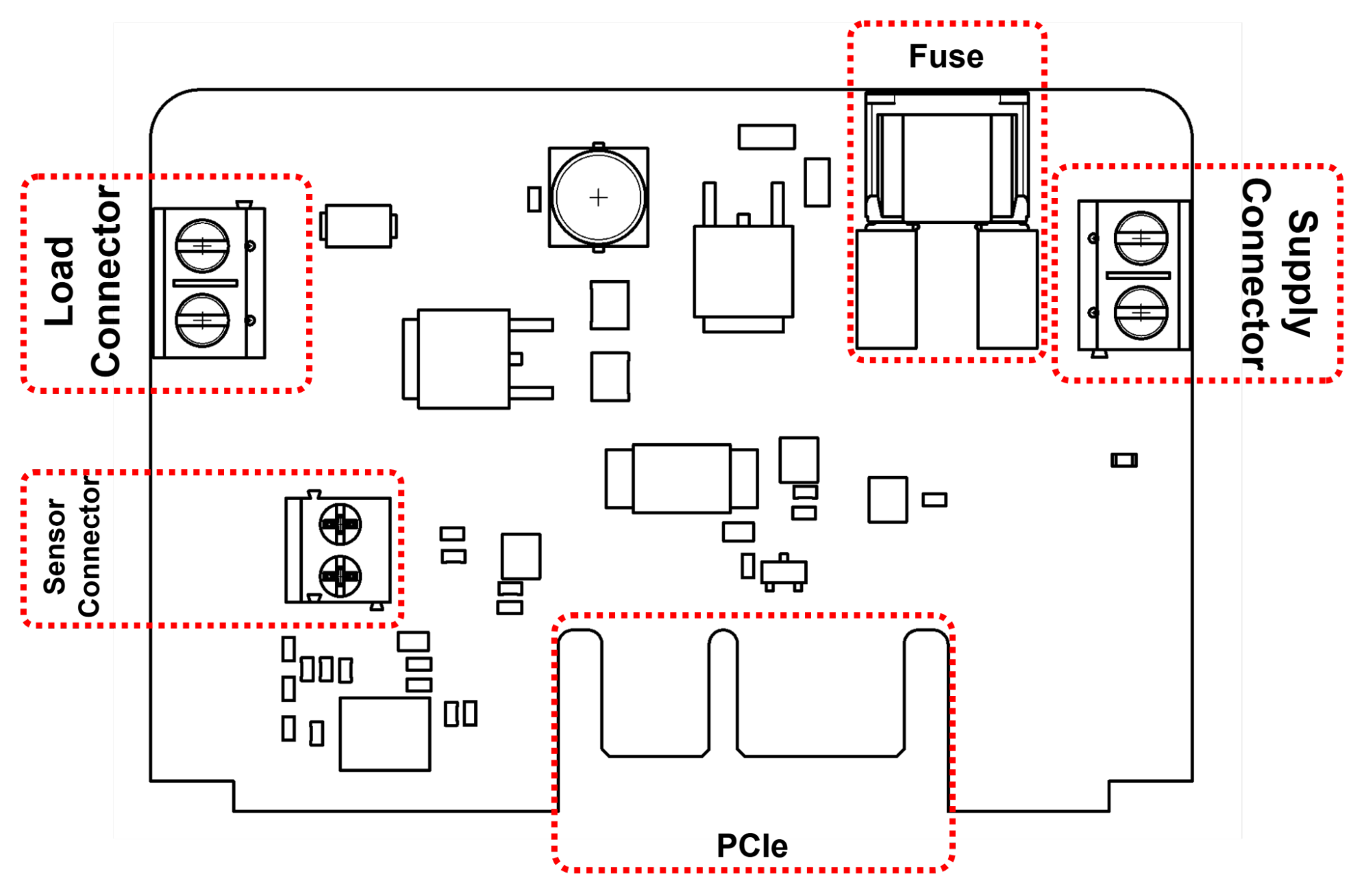
| Connection | Connector | Suggested Wire |
|---|---|---|
| Load Connector | Screw Terminal | 14-22 AWG |
| Supply Connector | Screw Terminal | 14-22 AWG |
| Sensor Connector | Screw Terminal | 18-26 AWG |
| Fuse | Mini Blade Fuse | N/A |
| PCIe | N/A | N/A |
# Detailed connections
# Typical Wiring Diagram
# Supply Connector
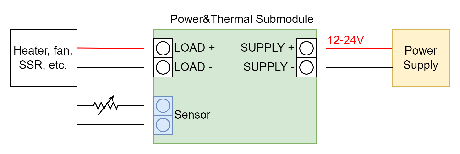
| SUPPLY + | Positive side of the supply that will power the load. It is rated 12V to 24V above SUPPLY -, with a maximum current draw of 10A. It is protected by a 15A blade fuse. |
| SUPPLY - | Negative side of the supply that will power the load. |
# Load Connector
| LOAD + | Positive side of the load connection |
| LOAD - | Negative side of the load connection |
# Sensor Connector
| Sensor (Any) | Connections for a temperature sensor (e.g. thermistor, 2-wire PT100) |
| Sensor (Any) | Connections for a temperature sensor (e.g. thermistor, 2-wire PT100) |
# PCIe Connector
The PCIe connector can be connected to any of the IO Module ports.
# LEDs
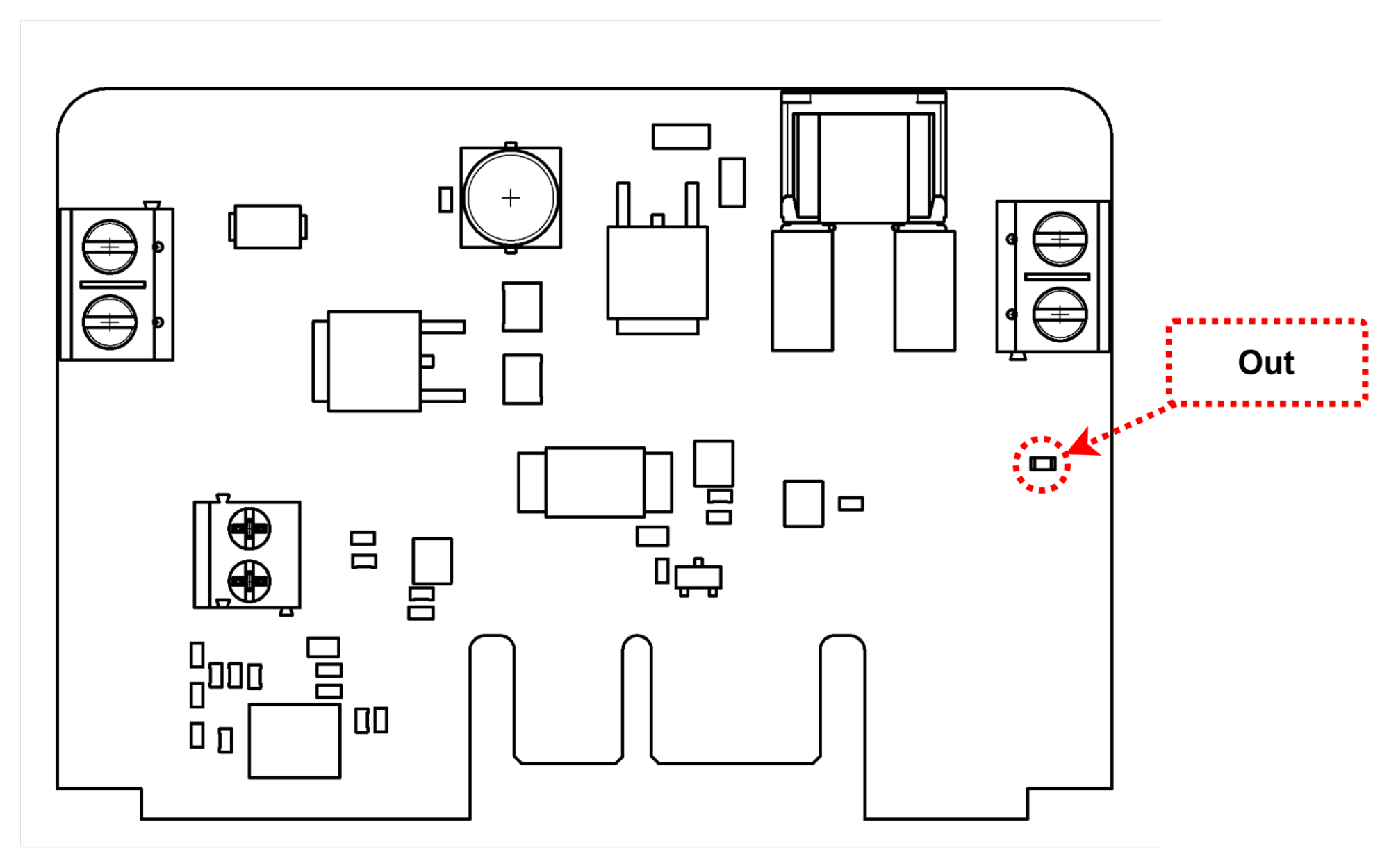
A status LED shows if the output is toggled on or off.
# Using Fans with Power&Thermal Submodule
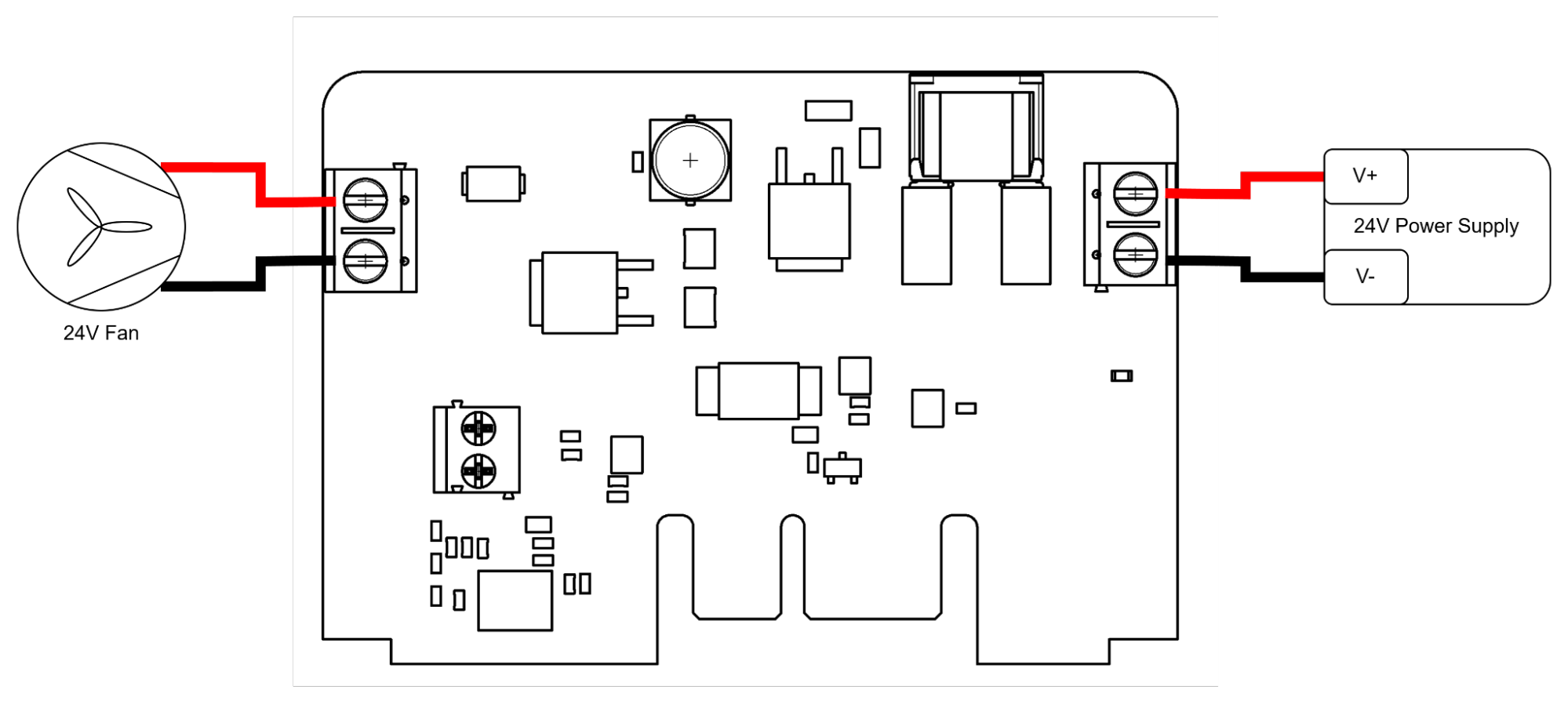
There are two ways of wiring a fan to a Power&Thermal Submodule. The submodule can either switch entirely the power from the fan, reducing the actual RPM. Another option is to use a fan with a PWM wire to better control the RPM. Using the PWM wire is preferred as it is much more reliable and predictable. Switching the power may not work in some cases, or may lead to a very poor consistency and range of RPM.
# Using a PWM pin (preferred)
Some fans have PWM control to precisely set the fan RPM. This control wire is often blue, but the color varies from one manufacturer to another. These fans usually have 4 wires (V+, V-, Tach, PWM), and sometimes 3(V+, V-, PWM). Some fans will accept the same voltage for the PWM control as the power input, but others will have lower voltage requirements. Two circuits will be detailed below.
In some cases such as for part cooling, the fan chosen should not rotate with a 0% PWM signal. Orion Fans makes such models, such as the OD1238-12HBXJ10A which is a 120mm fan with no rotation at a 0% duty cycle. Otherwise, the Switching power directly method should be used.
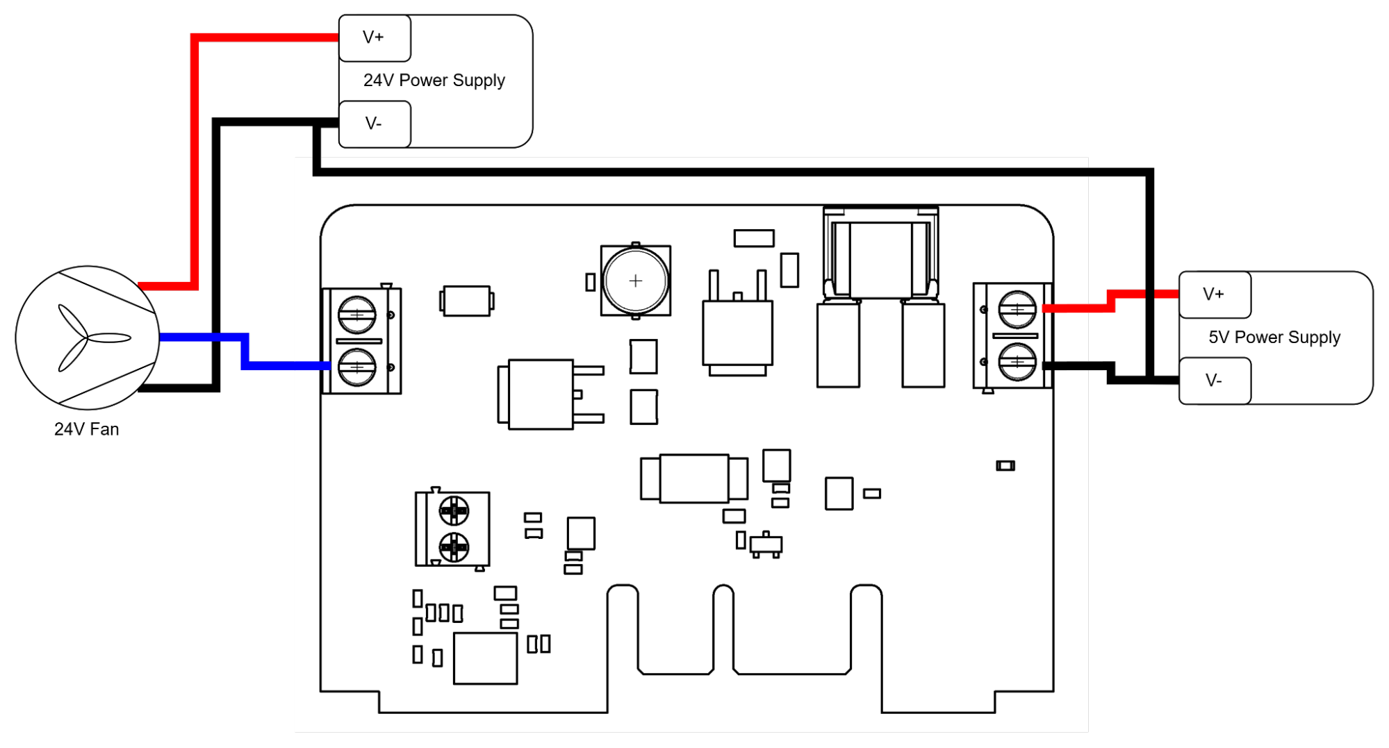
For example, a 40mm PWM fan from Same Sky (Formerly CUI Devices) with PN CFM-4010-13-22 is rated for 12VDC for power, but the signal voltage for the PWM control is only rated for 4-5V. The Fan would be connected as shown below:
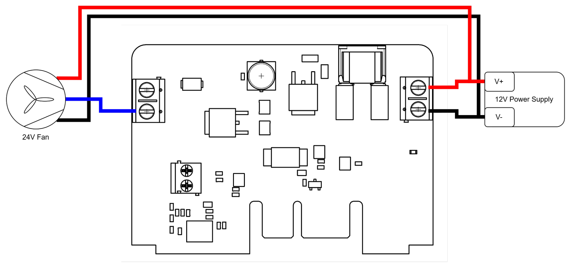
Another example with the 92mm fan from Delta Electronics with PN AUB0912VH-CX09 is shown below. The fan is 12V and the PWM control signal must be between 2.8VDC and 20VDC according to its specification sheet. The circuit would look as follow:
| ⚠️ | Always check your manufacturer for specifications regarding the cable color and PWM voltage requirements. |
|---|
# Switching power directly
This solution is not ideal, as the result may vary greatly from one fan to another, even if they come from the same manufacturer. In some cases, we’ve seen fans that wouldn’t turn with a PWM lower than 99%, and couldn’t control other than ON or OFF. In summary, the fan should be tested and isn't guaranteed to be controllable in RPM using this technique.
The “Supply Connector” should be connected to a power supply rated according to the fan specifications.