
# Laser Submodule
The Laser Submodule is a specialized module designed for precise height measurement applications and seamless integration with the Keyence IL-1000 and LK-G5001 laser amplifiers. The module enables essential functionalities such as laser activation/deactivation, LOW/HIGH judgment signals, alarm signaling, and 4mA to 20mA analog input for accurate measurements.
# Overview
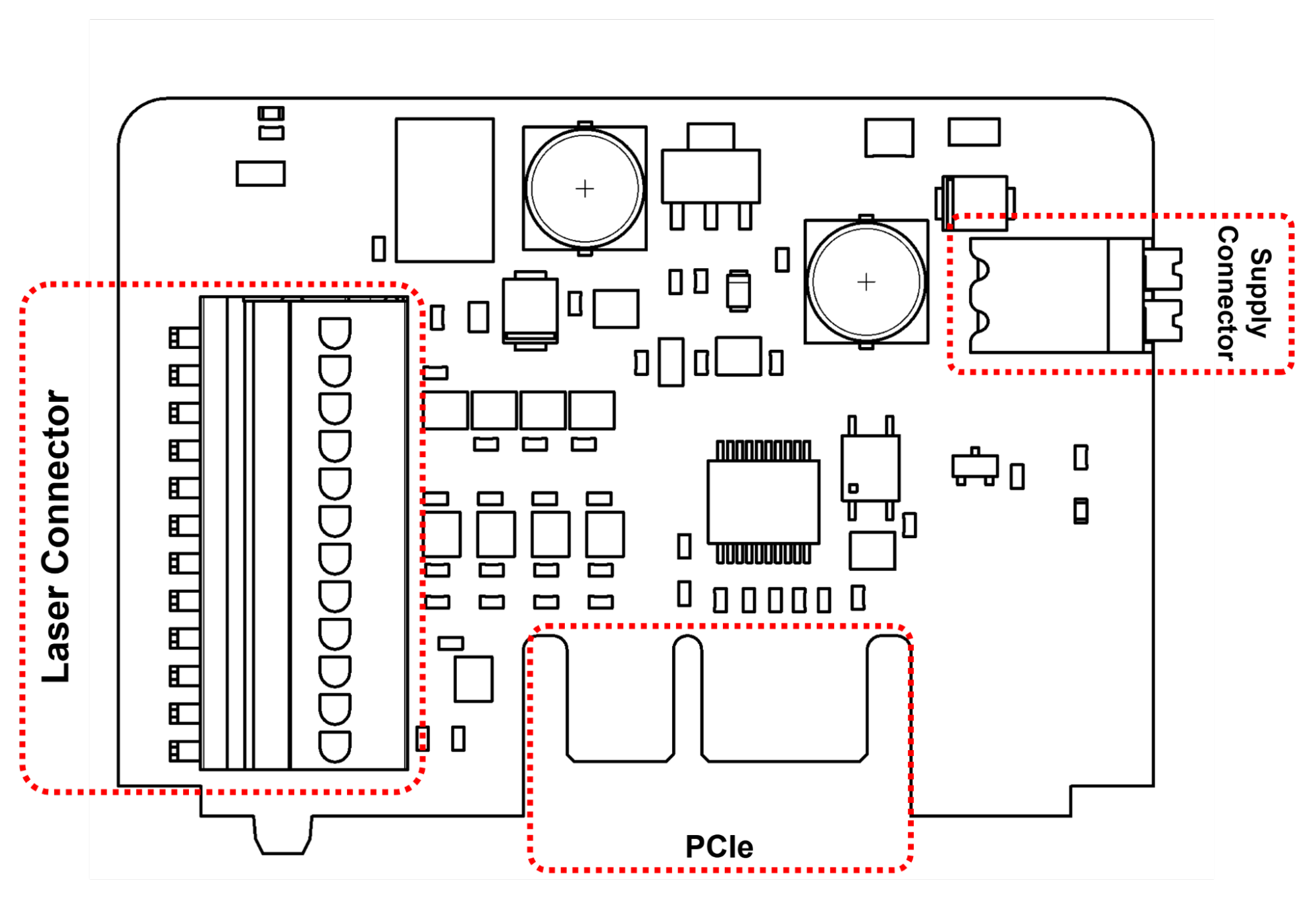
# Cables and connectors
| Connection | Connector | Suggested Wire |
|---|---|---|
| Laser Connector | Screw Terminal | 14-22 AWG |
| Supply Connector | Screw Terminal | 14-22 AWG |
| PCIe | N/A | N/A |
# Detailed connections
# Laser Connector
| V+ | Positive side of the Laser voltage supply |
| V0 | Negative side of the Laser voltage supply |
| ZSHFT | Reserved for future use. |
| MIT | Reserved for future use. |
| ENA | Enable the laser |
| LO_JDG | Reserved for future use. |
| HI_JDG | Reserved for future use. |
| AGND | Analog Ground |
| A_INPUT | Analog Input |
# Supply Connector
| SUPPLY + | Positive side of the Laser Power Input |
| SUPPLY - | Negative side of the Laser Power Input |
# PCIe Connector
The PCIe connector can be connected to a I²C port on the IO Module.
# Example with LK-G5001
Wiring:
| Laser 12 Pin terminal | SubModule Laser |
|---|---|
| Pin 1 (24 VDC (-)) | V0 (0V) |
| Pin 2 (24 VDC(+)) | V+ |
| Pin 4 (LASER_CTRL1) | ENA |
| Laser 6 Pin terminal | SubModule Laser |
|---|---|
| Pin 4 (OUT01 0 V) | AGND |
| Pin 5 (OUT01 (A)) | A_input |
| SubModule Laser Supply Connector | |
|---|---|
| 24V | 24V |
| GND | GND |
# Example with IL-1000
Wiring:
| IL-1000 wires | SubModule Laser |
|---|---|
| Blue | V0 (0V) |
| Brown | V+ |
| Purple (External input) *1 | ENA |
| IL-1000 light blue coaxial cable *2 | SubModule Laser |
|---|---|
| Shield | AGND |
| Orange | A_input |
| SubModule Laser Supply Connector | |
|---|---|
| 24V | 24V |
| GND | GND |
*1: The input has to be configured as the enable pin in the Laser controller
*2: The output has to be configured as a 0-20mA current output
Software settings:
Using LK-Navigator2 (opens new window) software:
In the "General settings" page of the "Head Settings" tab, change the following value :
- Measurement mode : Transparent object-2
- Reflection type selection mode : specular reflection
In the "Display, Analog" page of the "OUT Settings" tab put the following value :
- Measurement value1 : -6.000mm
- Output voltage1 : -10.000V
- Measurement value2 : 6.000mm
- Output voltage2 : 10.000V
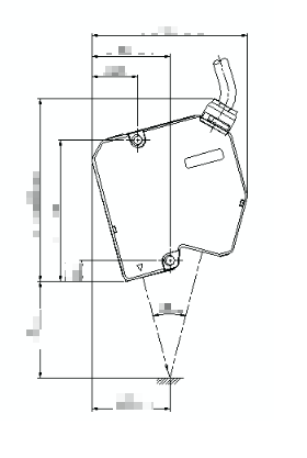
These settings have been designed to work well with both transparent and opaque materials. The sensor head needs to be mounted at a tilt. Refer to the datasheet for the mounting diagram.
Tilted mounting example:
# LEDs
A Laser Power LED shows if the Laser has power and a 3.3V LED shows if the logic voltage is correct.