
# IO Module
# Overview
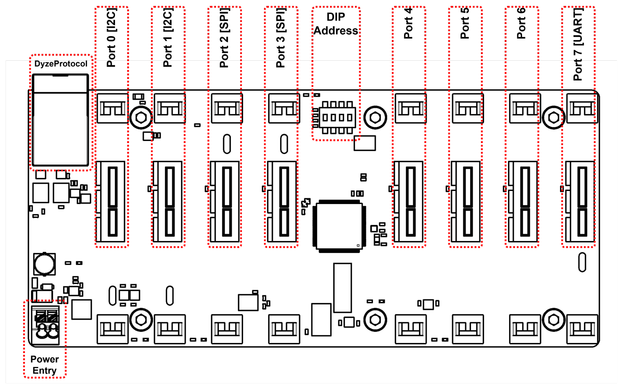
The IO Module has many inputs and outputs and it is critical to understand their purpose and usage before attempting to wire the board. Each connection will be described in detail.
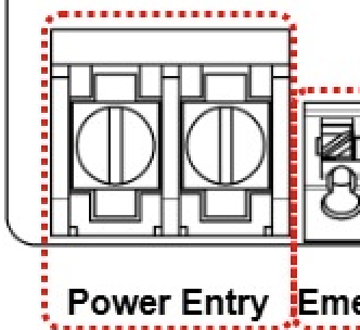
- Power Entry: Main power input for the Aurora
- DyzeProtocol: Aurora peripherals network for modules
- Ports 0-7 for submodules
- 2* I2C capable ports
- 2* SPI capable ports
- 1* UART capable port
# Cables and connectors
| Connection | Connector | Suggested Wire |
|---|---|---|
| Power Entry | Screw Terminal | 16-24 AWG |
| DyzeProtocol | RJ45 Shielded | Cat5E or better |
| Ports | PCIe x1 | N/A |
# Detailed connections
# Power Entry
| 24V | GND |
|---|---|
| +24V only | Power ground |
| ⚠️ | The power must not be interrupted by the emergency switch. The IO Module must stay powered while other devices are shut down for security. |
|---|
# DyzeProtocol
See DyzeProtocol.
# LEDs
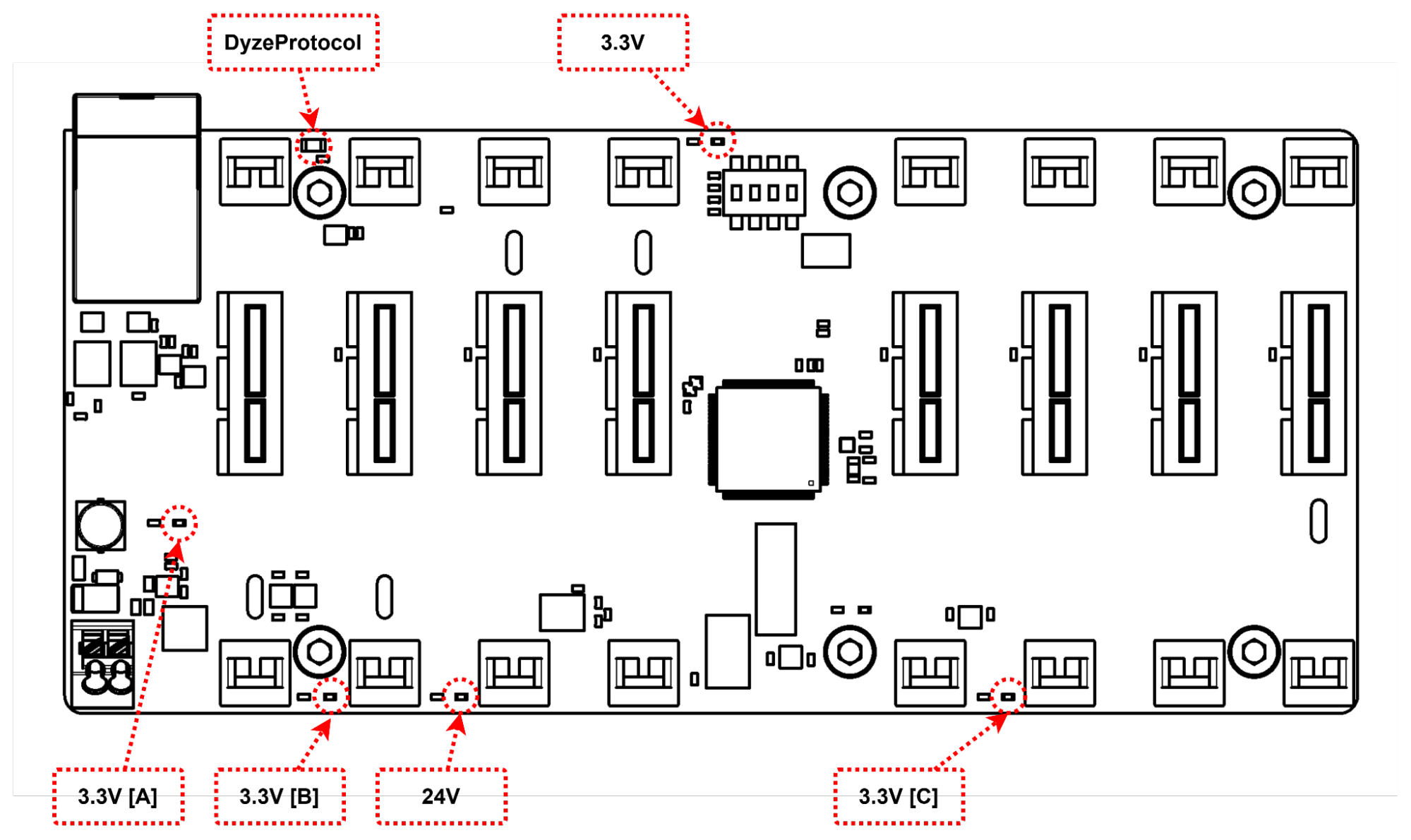
The IO Module features a few LEDs to indicate status information.
- Power LEDs: 5 green LEDs that should be continuously lit when the IO Module is powered (24V, 3V3, 3V3A, 3V3B, 3V3C)
- Dyze Protocol LED: yellow LED that blinks when connected to the Dyze Protocol
# DIP Switches
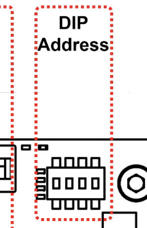
Use the DIP switches on the Step-Dir Module to set its ID according to the following table.
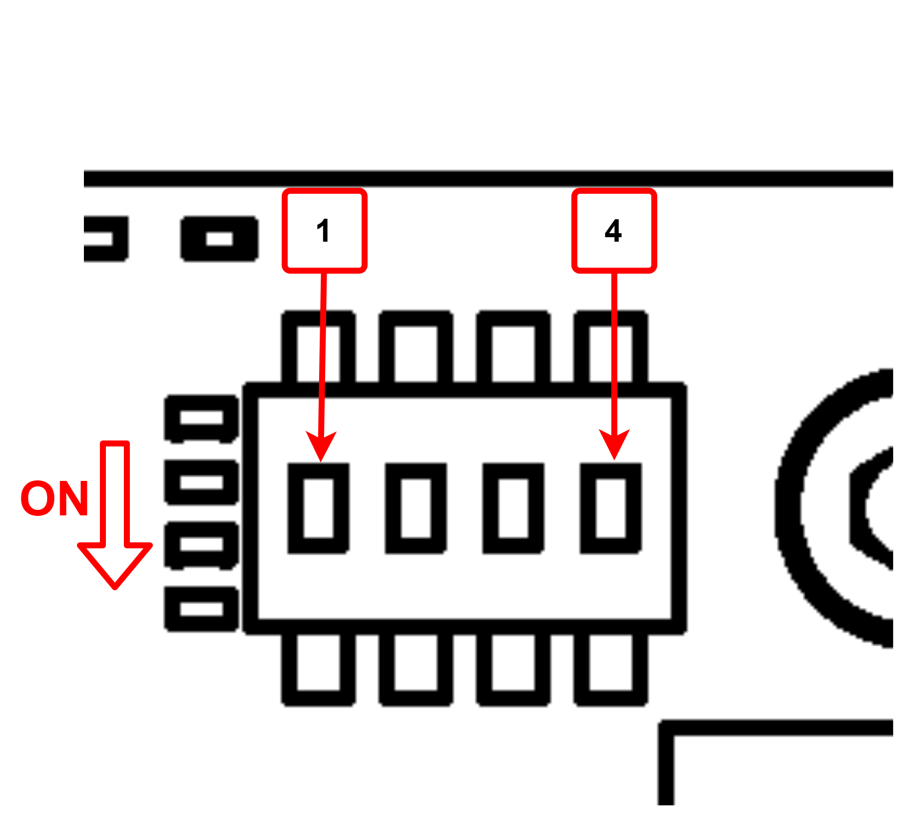
| S1 | S2 | S3 | S4 | ID | S1 | S2 | S3 | S4 | ID |
|---|---|---|---|---|---|---|---|---|---|
| OFF | OFF | OFF | OFF | 1 | ON | OFF | OFF | OFF | 9 |
| OFF | OFF | OFF | ON | 2 | ON | OFF | OFF | ON | 10 |
| OFF | OFF | ON | OFF | 3 | ON | OFF | ON | OFF | 11 |
| OFF | OFF | ON | ON | 4 | ON | OFF | ON | ON | 12 |
| OFF | ON | OFF | OFF | 5 | ON | ON | OFF | OFF | 13 |
| OFF | ON | OFF | ON | 6 | ON | ON | OFF | ON | 14 |
| OFF | ON | ON | OFF | 7 | ON | ON | ON | OFF | 15 |
| OFF | ON | ON | ON | 8 | ON | ON | ON | ON | 16 |
← Aurora GPIO Submodule →