
# Step-Dir Module
The Step-Dir Module allows stepper motors to be used in a Dyze environment by acting as an interface between up to 4 stepper drivers and a Dyze Mainboard. The Step-Dir Module also has encoder inputs that enable rotational feedback from the motors.
Once a successful connection is made with a Dyze Mainboard, the Step-Dir Module converts instructions sent to it via the Dyze Protocol into appropriate stepper control signals.
# Overview
The Step-Dir Module requires a single 24VDC power input (fused, 250mA) and can support up to 4 stepper motors; it can control up to 4 stepper drivers and read up to 4 encoders. The stepper drivers must be powered separately according to their voltage and current needs.
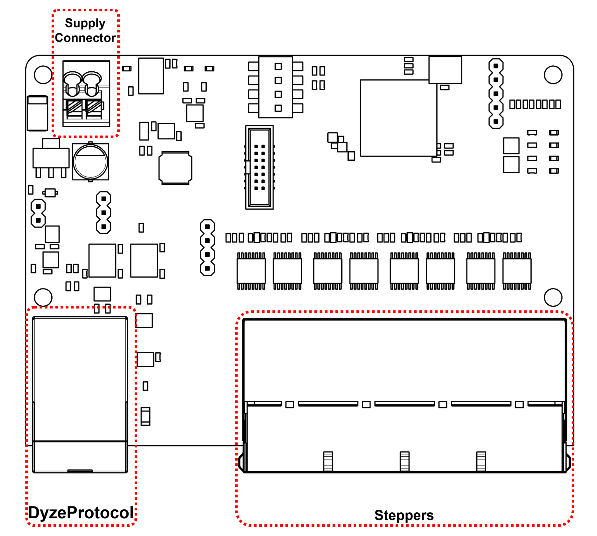
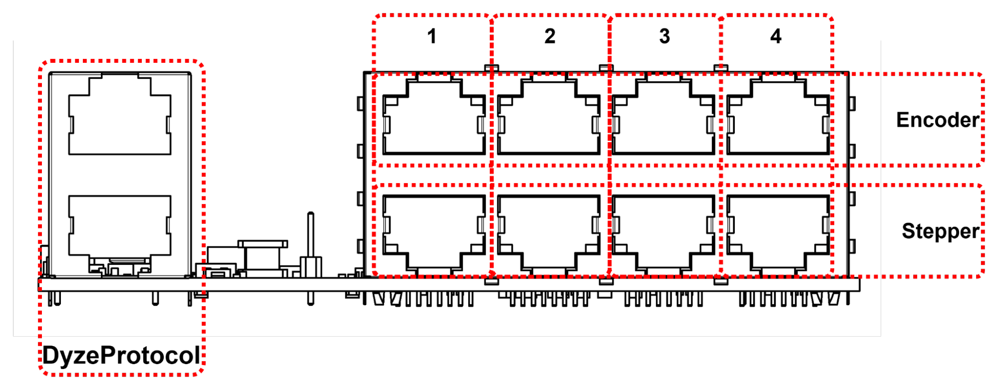
| ⚠️ | The Step Dir Module uses RJ45 connectors for multiple ports, each with a unique wiring configuration. Ensure that the correct connector is plugged into the designated port to prevent potential circuit damage. |
|---|
# Cables and connectors
| Connection | Connector | Suggested Wire |
|---|---|---|
| Power Entry | Screwless Terminal | 16-24 AWG |
| DyzeProtocol | RJ45 Shielded | Cat5E or better |
| Steppers | RJ45 | Cat5 or better |
| Encoders | RJ45 | Cat5 or better |
# Detailed connections
# Power Entry
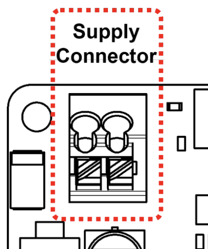
| 24V | GND |
|---|---|
| +24V only | Power ground |
# DyzeProtocol
See DyzeProtocol.
# Stepper
| ⚠️ | The Step-Dir Module sends signals to 4 stepper motor drivers, but it doesn't directly power the stepper motor. Users must select appropriate stepper motor drivers to power their stepper motors. |
|---|
# General Wiring
The Step-Dir Module allows up to 4 stepper drivers to be connected to a stepper motors. The stepper drivers are connected to the Step-Dir Module using the RJ45 connectors. The stepper motors are connected to the stepper drivers using their appropriate connectors. The encoder are optional. If they are available, they should be connected to the matching encoder inputs (same port number) using the RJ45 connector.
| ⚠️ | The Replay Cloud feature will be disabled if encoders are not present, as motor positions cannot be logged. |
|---|
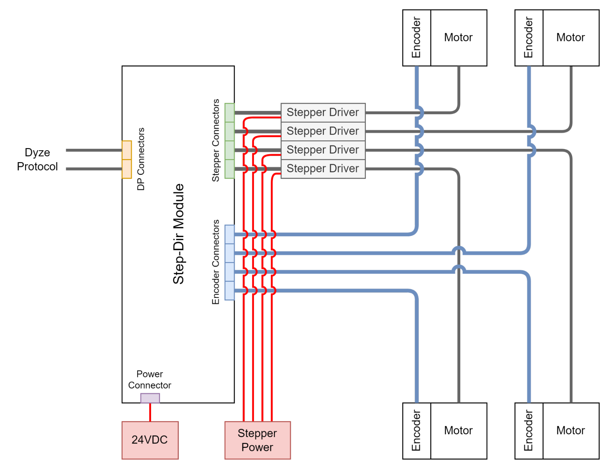
The wiring scheme above presents a typical setup for connecting a stepper motor to the Step-Dir Module. The encoders are supplied by 5V outputs on the Step-Dir Module, and these outputs are protected by 100mA-rated resettable fuses.
# RJ45
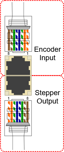 | Encoder Input Pin 1 - Orange White Index + Pin 2 - Orange Index - Pin 3 - Green White 5V Pin 4 - Blue B- Pin 5 - Blue White B+ Pin 6 - Green GND Pin 7 - Brown White A+ Pin 8 - Brown A- |
|---|---|
| Stepper Output Pin 1 - Orange White Direction + Pin 2 - Orange Direction - Pin 3 - Green White GND Pin 4 - Blue Enable - Pin 5 - Blue White Enable + Pin 6 - Green GND Pin 7 - Brown White Step / Pulse + Pin 8 - Brown Step / Pulse - |
# Stepper Driver Outputs
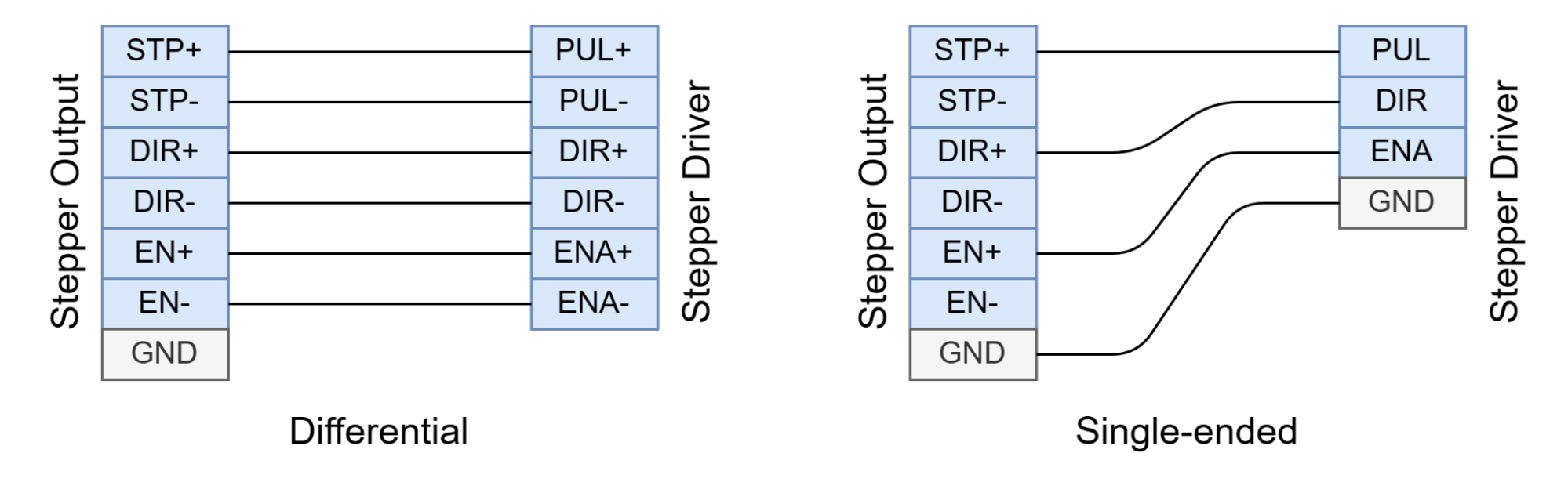
The differential circuit outputs 3.1V in differential and 3.4V in single ended. Ensure that your drive is compatible with these voltage ratings.
The wiring of the stepper driver outputs can be configured to be made compatible with both differential or single-ended inputs by connecting or not the negative output of each control signal. Refer to the following diagrams.
# Active-high ENABLE output
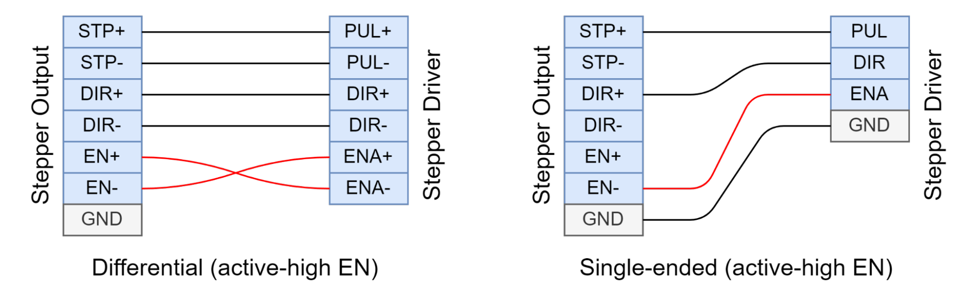
The Step-Dir Module currently has an active-low ENABLE output. It is possible to make it active-high by swapping the EN+ and EN- connections.
As an example, the enable pin for the Dyze Stepper Driver must always be inverted, as it is an active-low input and be configured as single ended. For our stepper driver, the diagram below should be followed (Single-Ended, Active High Enable).
# Encoder Inputs
The Step-Dir Module is only compatible with encoders that have differential outputs.
# LEDs
The Step-Dir Module features a few LEDs to indicate status information.
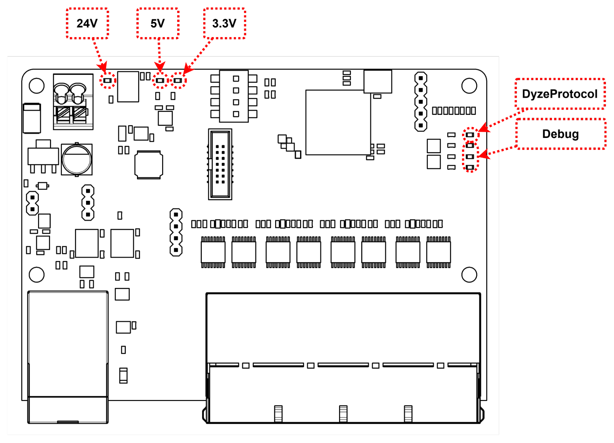
- 24V, 5V and 3.3V green LEDs: should be fully lit when the Step-Dir Module is powered by 24VDC.
- Dyze Protocol (DP) yellow LED: blinks when connected to the Dyze Protocol
- 1, 2 and 3 red LEDs: reserved for debugging
# DIP Switches
Use the DIP switches on the Step-Dir Module to set its ID according to the following table.
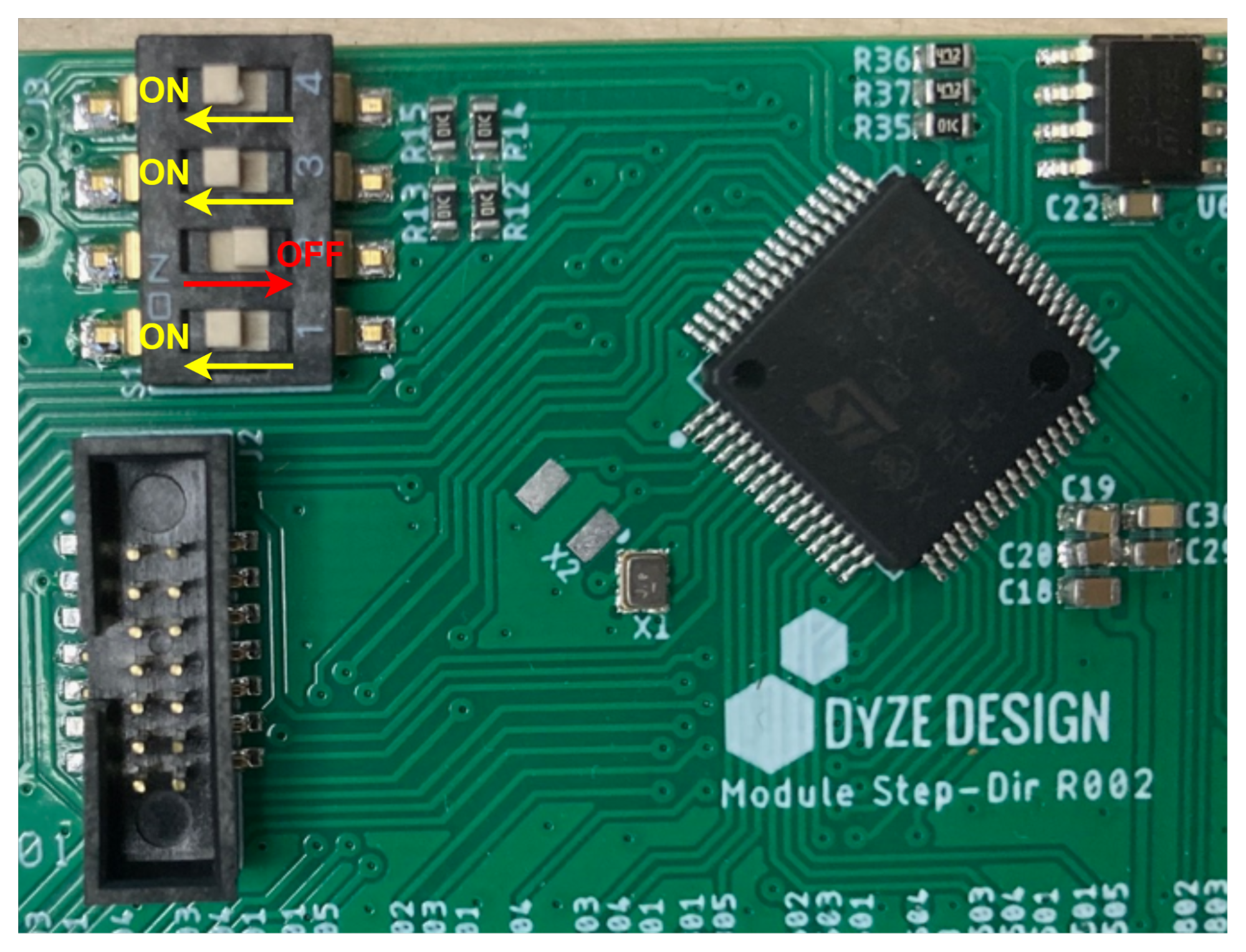
When looking at the image above, the switches are read bottom to top (1 to 4): ON-OFF-ON-ONp
| S1 | S2 | S3 | S4 | ID | S1 | S2 | S3 | S4 | ID |
|---|---|---|---|---|---|---|---|---|---|
| OFF | OFF | OFF | OFF | 1 | ON | OFF | OFF | OFF | 9 |
| OFF | OFF | OFF | ON | 2 | ON | OFF | OFF | ON | 10 |
| OFF | OFF | ON | OFF | 3 | ON | OFF | ON | OFF | 11 |
| OFF | OFF | ON | ON | 4 | ON | OFF | ON | ON | 12 |
| OFF | ON | OFF | OFF | 5 | ON | ON | OFF | OFF | 13 |
| OFF | ON | OFF | ON | 6 | ON | ON | OFF | ON | 14 |
| OFF | ON | ON | OFF | 7 | ON | ON | ON | OFF | 15 |
| OFF | ON | ON | ON | 8 | ON | ON | ON | ON | 16 |