# GPIO Submodule
While there are two inputs available on the external screw terminal (see pinout below), only one of them can be used as they are not independent from each other.
The inputs are each low-pass filtered up to a frequency of 8.7kHz.
# Overview
# Cables and connectors
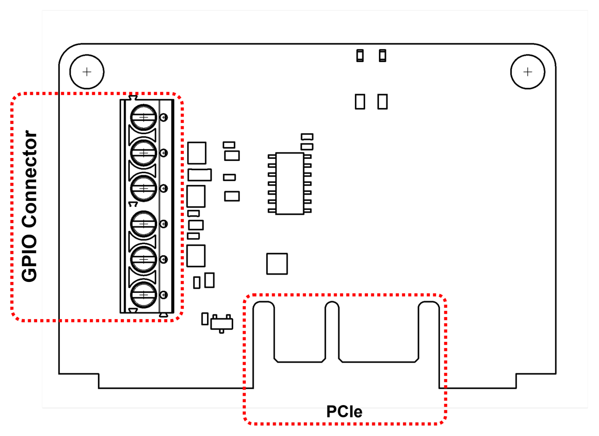
| Connection | Connector | Suggested Wire |
|---|---|---|
| GPIO Connector | Screw Terminal | 16-24 AWG |
| PCIe | N/A | N/A |
# Detailed connections
# GPIO Connector
| GND | Ground connection |
|---|---|
| 24V | 24V supply, maximum 500 mA current draw |
| 3V3 | 3.3V supply, maximum 100 mA current draw |
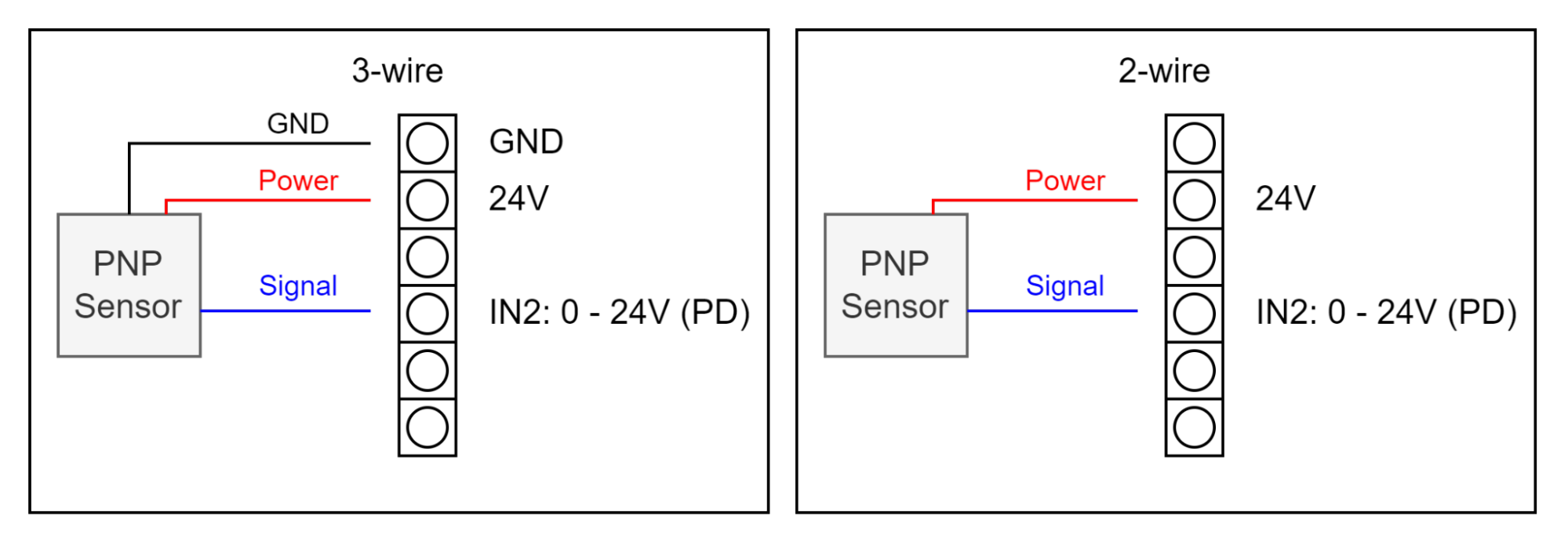
| IN2: 0 - 24V (PD) | Digital input with integrated pull-down, 24V maximum input voltage. For use with a PNP capacitive or inductive sensor. |
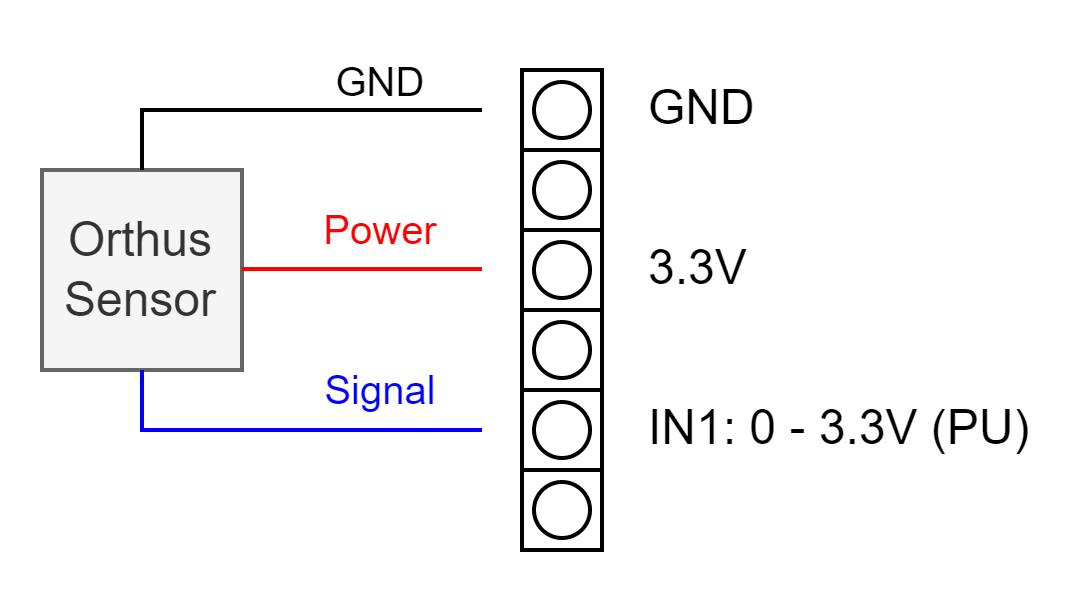
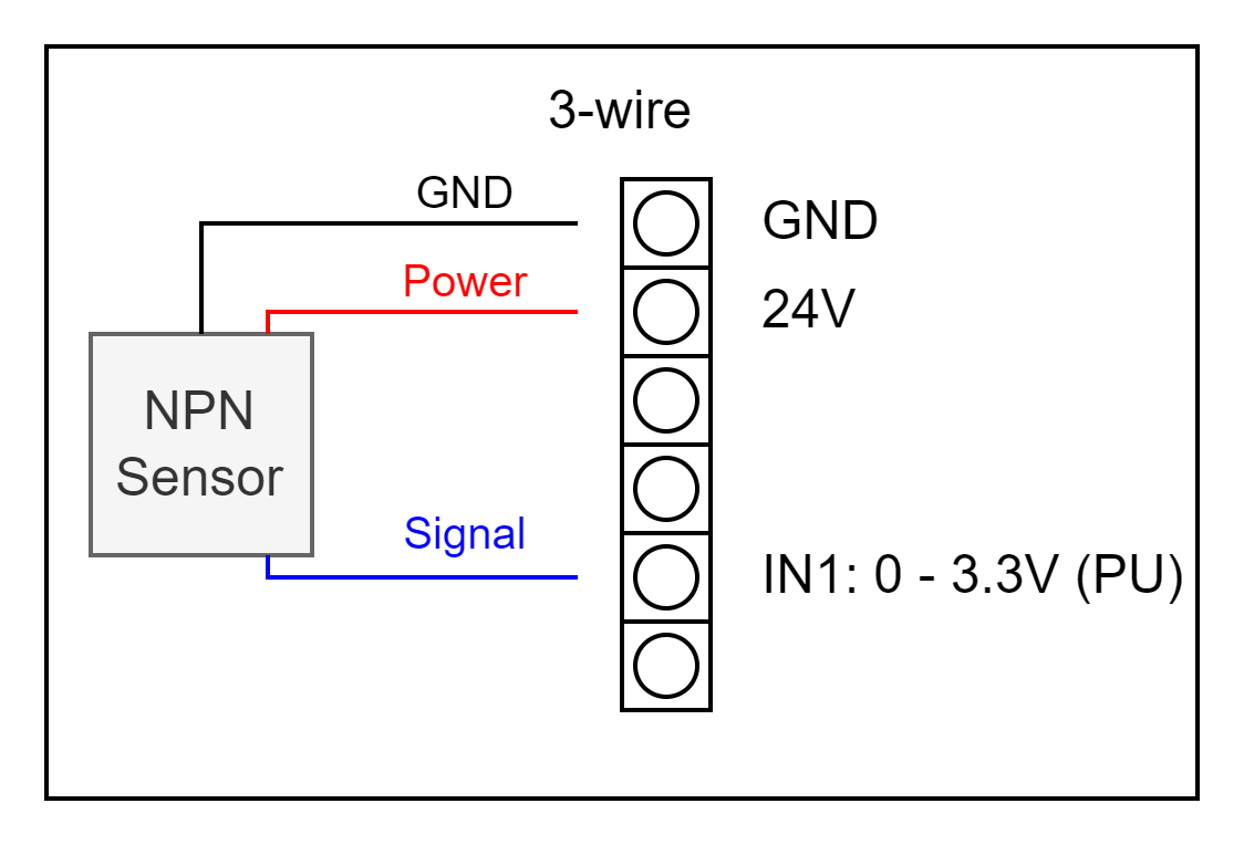
| IN1: 0 - 3V3 (PU) | Digital input with integrated pull-up, 3.3V maximum input voltage. For use with an Orthus sensor, an NPN capacitive or inductive sensor, a button or a limit switch. |
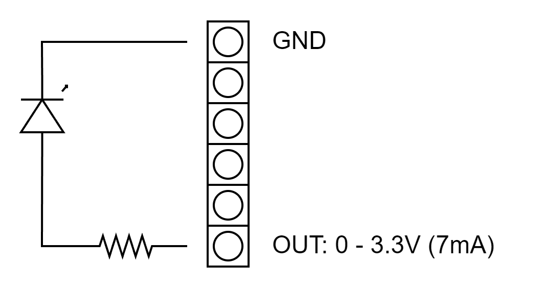
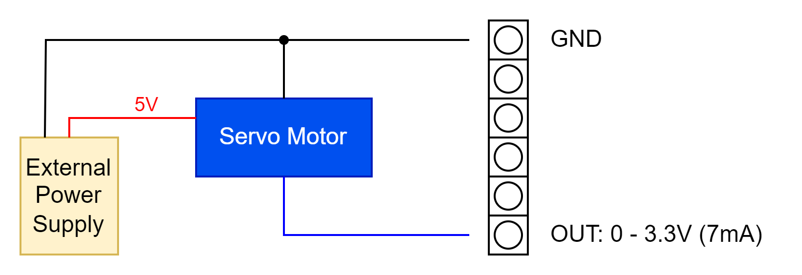
| OUT: 0 - 3V3 (7mA) | Digital output connected directly to the IO Module MCU with a maximum allowed current draw of 7mA, at 3.3V, capable of PWM. |
# Orthus Sensor
# Button/Limit Switch
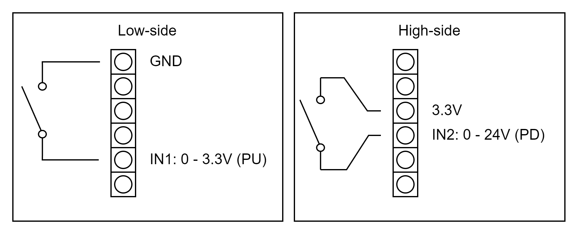
# PNP Capacitive/Inductive Sensor
# NPN Capacitive/Inductive Sensor
# LED
# RC Servo Motor
# PCIe Connector
The PCIe connector can be connected to any of the IO Module ports.
# LEDs
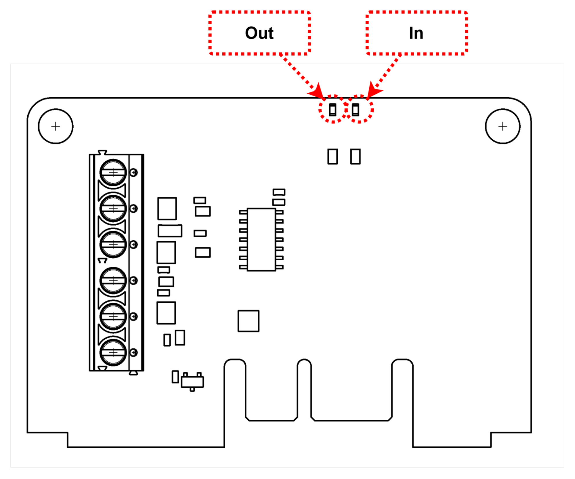
Two LEDs are installed on the GPIO Submodule. They represent the state of the output (Out) coming from the IO Module and the input (In) going into it.